Switching device

a technology of switching device and push button, which is applied in the direction of transmission, substation equipment, instruments, etc., can solve the problems of poor operability of the jog dial and the two push buttons disposed in the foregoing manner, and achieve the effect of improving operability

Inactive Publication Date: 2005-03-01
SONY CORP +1
View PDF6 Cites 32 Cited by
  • Summary
  • Abstract
  • Description
  • Claims
  • Application Information

AI Technical Summary

Benefits of technology

It is therefore an object of the present invention to provide a switching device having one actuator ...

Problems solved by technology

However, the above jog dial and two pushbuttons disposed in the foregoing manner are problematic for their poor operability.
However, the jog dial and the push...

Method used


Image

  • Switching device
  • Switching device
  • Switching device

Examples


Embodiment Construction

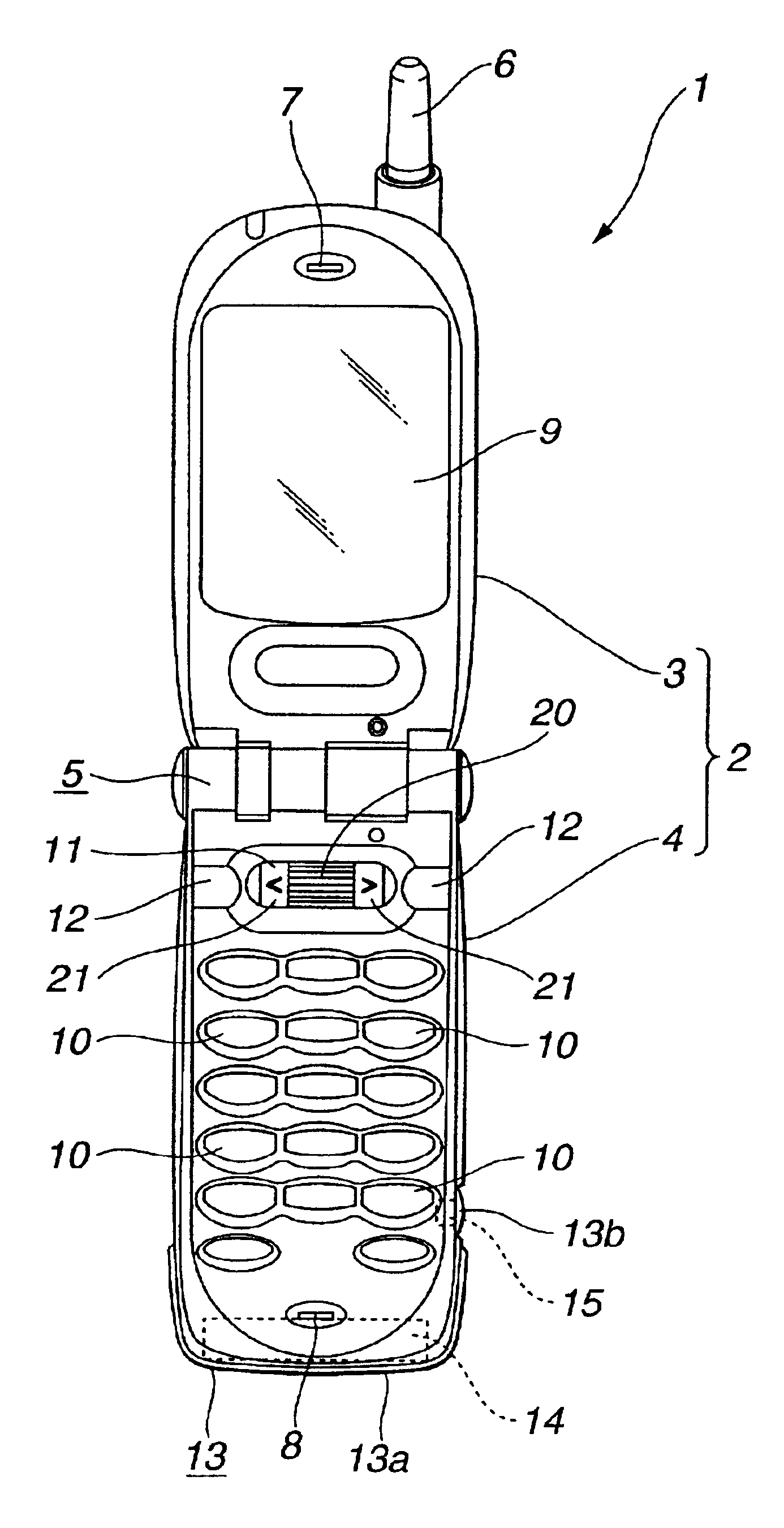
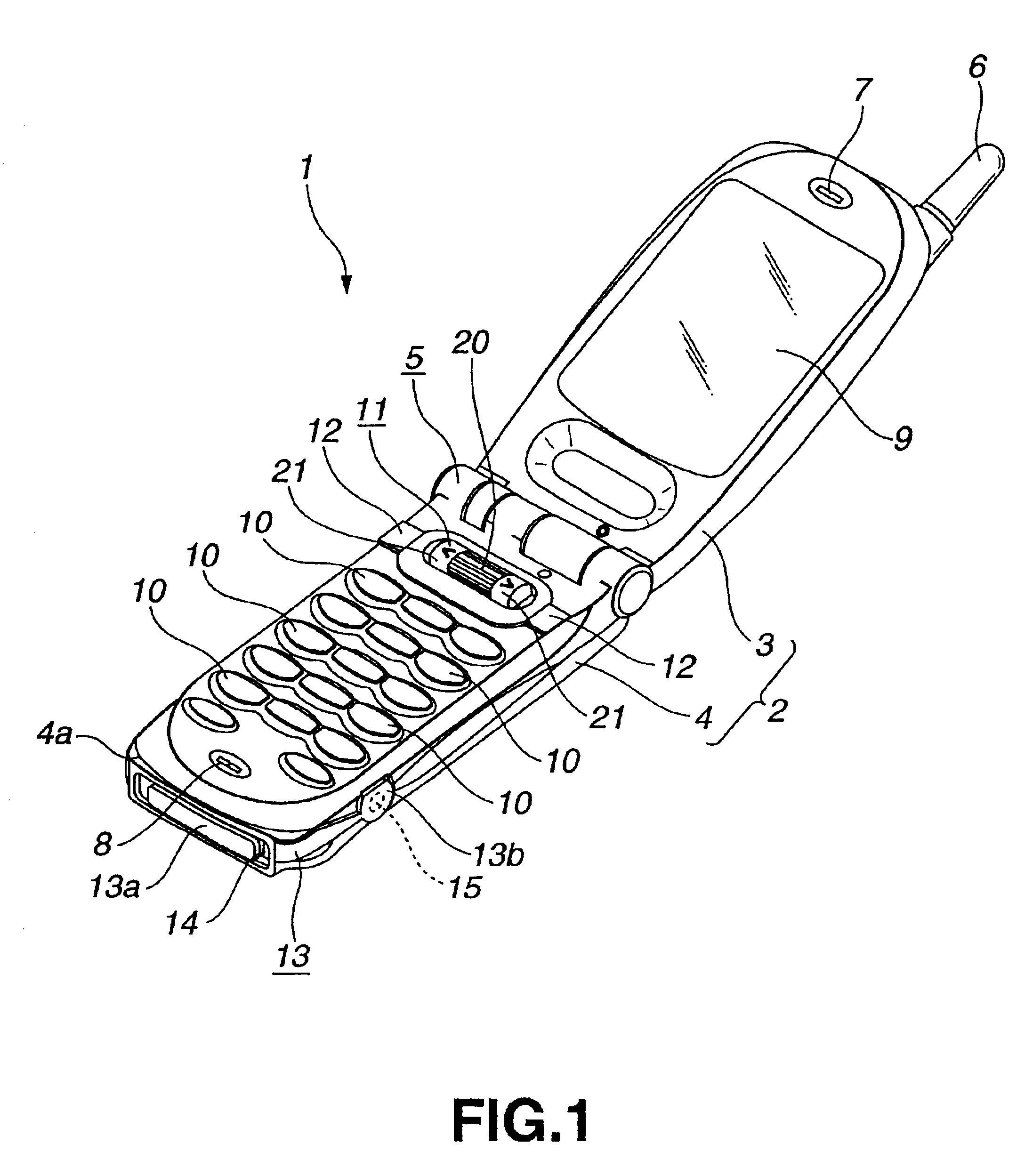
It should be noted that in the embodiments of the switching device according to the present invention includes a jog dial of a portable telephone and two actuators disposed apart from a dial being the actuator of the jog dial on both its sides as shown in the accompanying drawings.

First there will briefly be described the portable telephone as a handy electronic device employing the switching device according to the present invention.

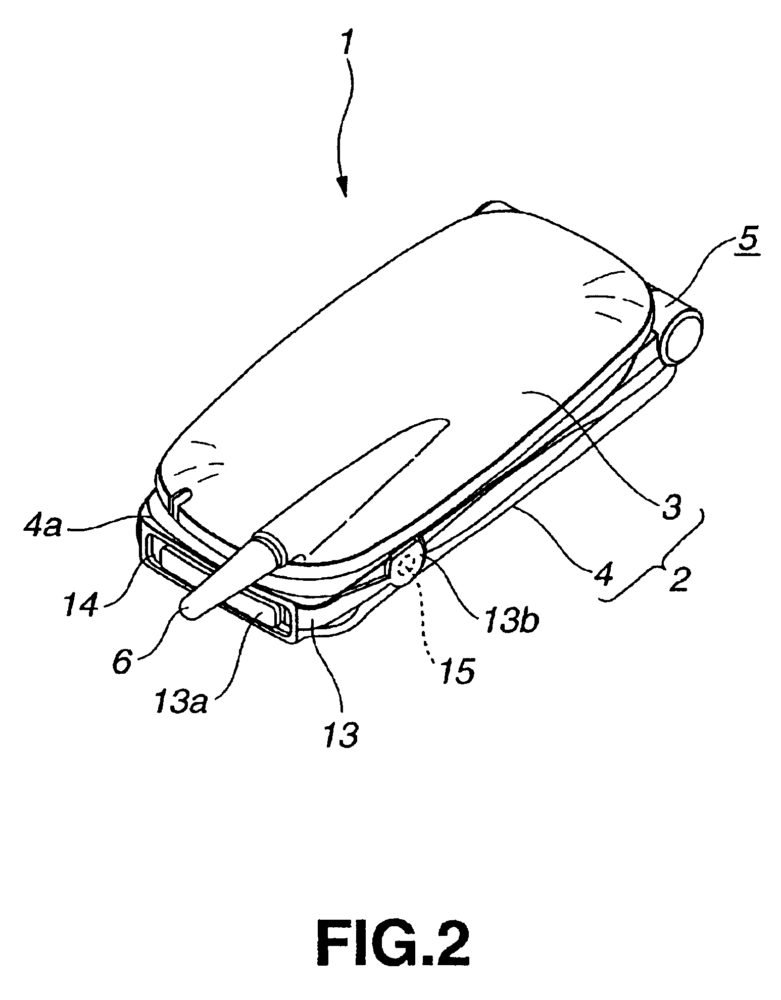
The portable telephone is generally indicated with a reference 1. As shown, the portable telephone 1 includes a body case 2 formed from a synthetic resin and in which various members are housed and installed.

The body case 2 consists of an upper half (will be referred to as “upper case” hereunder) 3 and lower half (will be referred to as “lower case” hereunder) 4. The upper case 3 is hinged (indicated at reference 5) at the lower end thereof to the upper end of the lower case 4. The upper and lower cases 3 and 4 are freely pivotable between a closed posi...


PUM


Abstract

A switching device having a central actuator and two outer actuators disposed separately from the central actuator on two sides, wherein the central actuator is a cylindrical dial (23) supported rotatably and depressibly by a pair of spindle bearings (26) included in a base plate; the base plate (25) supporting the dial (23) is fitted in a frame; the outer actuators are pivotable in a direction approximately perpendicular to a direction in which the three actuators are arrayed and about a pivot approximately perpendicular to a direction in which operating surfaces of the outer acutators are pushed to press a contact (30) disposed on the frame; and each of the outer actuators has a to-be-supported piece (34) extending to a position where the outer actuator deviates from a lateral edge of the dial (23) in the rotating direction as viewed from the front. The outer actuator is pivotally attached at the end of the to-be-supported piece (34) to the frame (22) and has a center axis crossing the pair of spindle bearings of the central actuator.

Description

BACKGROUND OF THE INVENTION1. Field of the InventionThe present invention generally relates to a technology to improve the operability of a switching device, and more particularly, to a switching device with three actuators disposed in an array on the top surface of a body.2. Description of the Related ArtConventional handy electronic devices such as portable telephones use a so-called jog dial as a switching device for selection of a plurality of options (processes).Also, there has been proposed a switching device with a jog dial and two pushbuttons disposed apart from the jog dial on both its sides. The two pushbuttons are used to set and carry out a desired one of the options, selected by the jog dial.However, the above jog dial and two pushbuttons disposed in the foregoing manner are problematic for their poor operability.The jog dial and two pushbutton switches are normally operated with the same finger (e.g., thumb). However, the jog dial and the pushbutton switches are not co...

Claims


Application Information

Patent Timeline
IPC IPC(8): G06F3/033H01H21/22H01H21/00H01H25/00H04M1/02H04M1/247H01H25/06H01H13/64H01H89/00
CPCG06F3/0362H01H21/22H04M1/0214H01H25/008H04M1/233H01H2019/146H01H13/64
Inventor SAWADA, MASAKIYORITSUNE, YASUHIROMORINISHI, YUSUKESUZUKI, HIROHITOHASEGAWA, TOMONORI
Owner SONY CORP
Why Eureka
Try Eureka