Pneumatic motor

a technology of pneumatic motors and motors, which is applied in the direction of positive displacement engines, mechanical equipment, machines/engines, etc., can solve the problems of increasing the likelihood of an individual part breaking and making the motor inoperable, virtually and/or practically impossible, and complicated pneumatic motor manufacturing

Inactive Publication Date: 2005-03-08
REHCO LLC
View PDF53 Cites 13 Cited by
  • Summary
  • Abstract
  • Description
  • Claims
  • Application Information

AI Technical Summary

Benefits of technology

The present invention may be designed as small as manufacturing allows as well as large as desired. The present invention may therefore find applicability in full-scale air compressed engines

Problems solved by technology

All of which complicates the manufacturing of the pneumatic motor and increases the likelihood that an individual part will break making the motor inoperable.
If a pneumatic motor is desired to be extremely small, say the

Method used


Image

  • Pneumatic motor
  • Pneumatic motor
  • Pneumatic motor

Examples


Embodiment Construction

While the invention is susceptible to embodiments in many different forms, there are shown in the drawings and will be described herein, in detail, the preferred embodiments of the present invention. It should be understood, however, that the present disclosure is to be considered an exemplification of the principles of the invention and is not intended to limit the spirit or scope of the invention and / or claims of the embodiments illustrated.

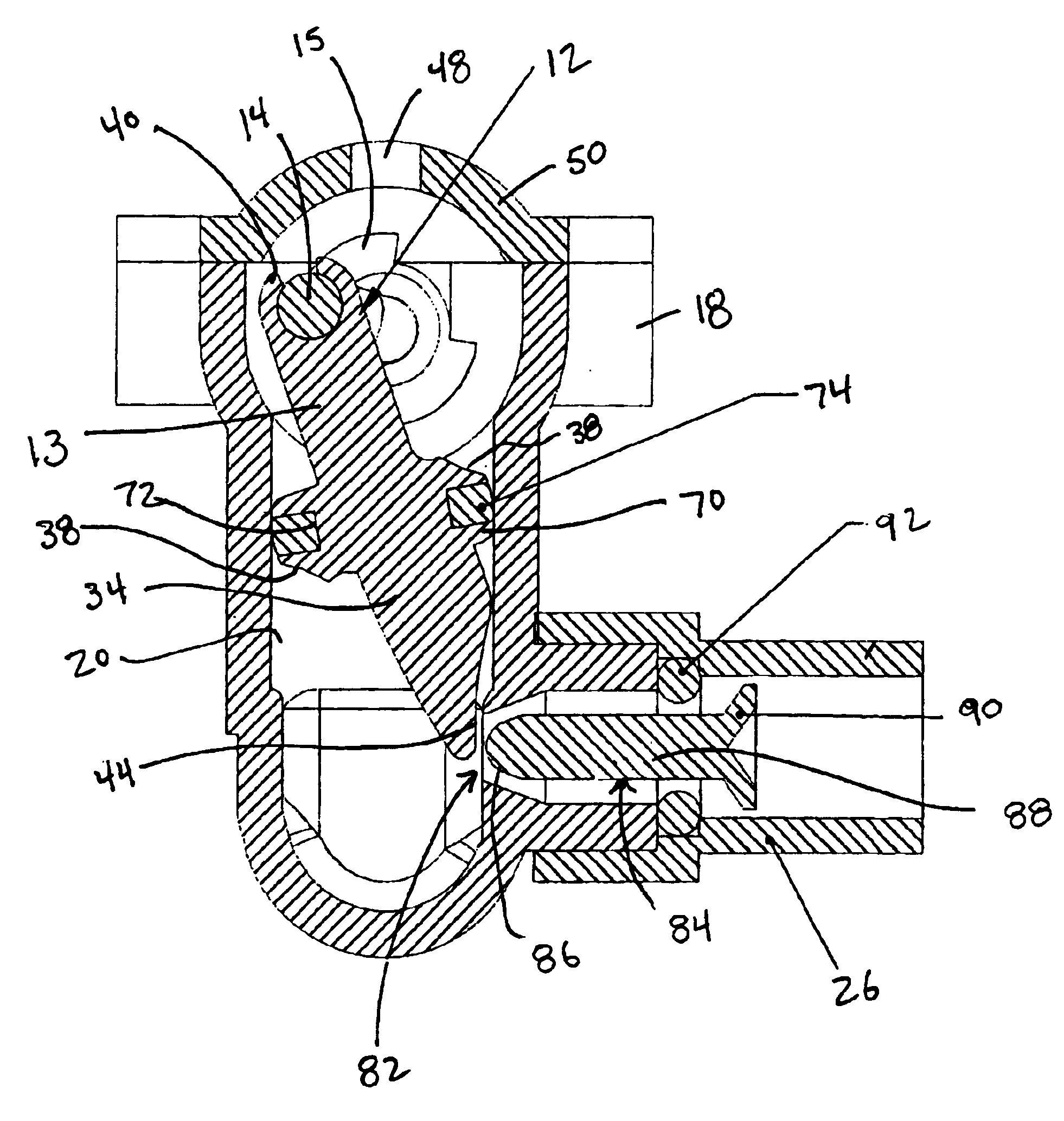
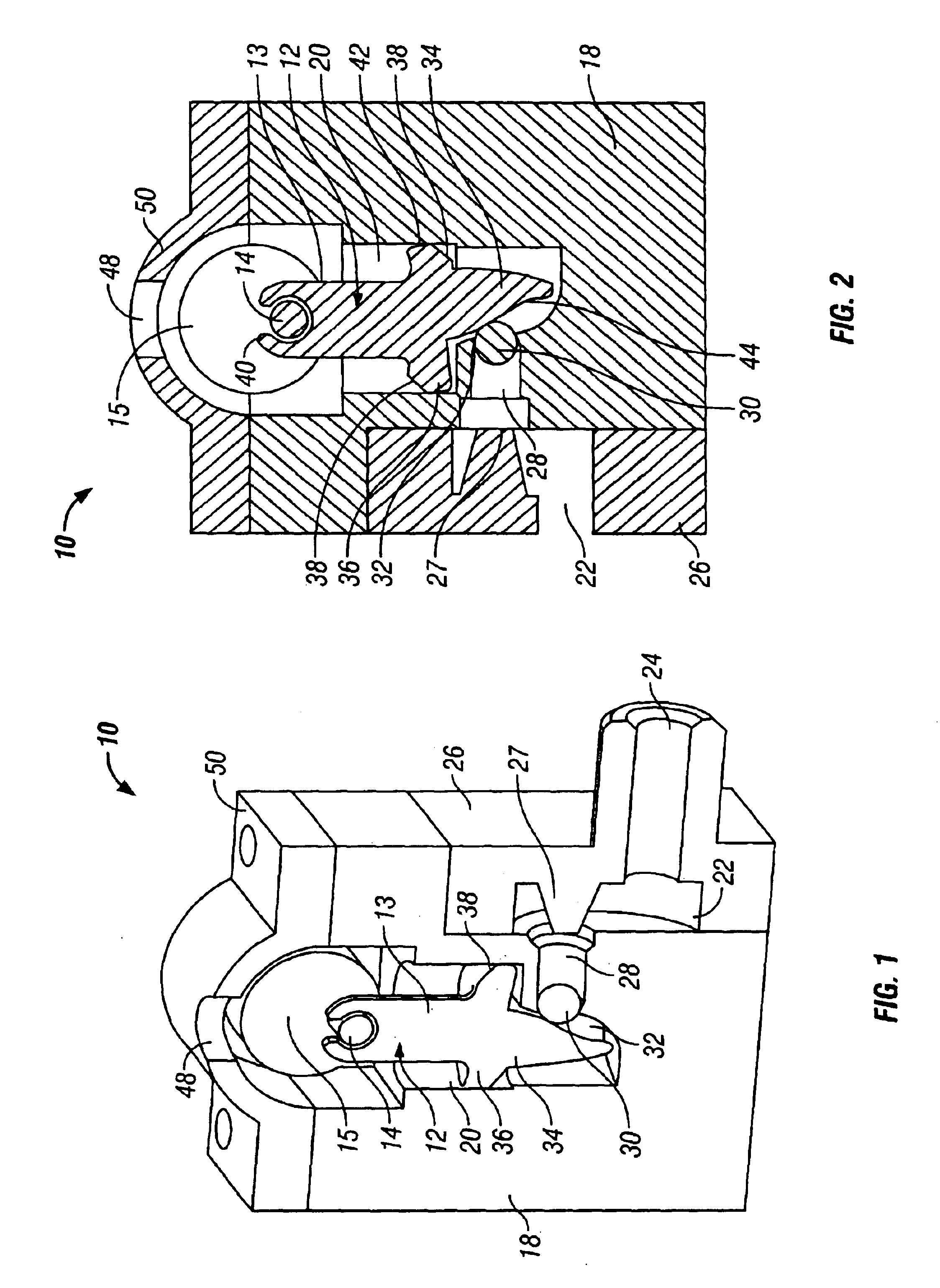
Referring now to FIGS. 1 and 2, a pneumatic motor 10 in accordance with one embodiment of the present invention includes a piston 12 attached to a crank shaft 14. The crank shaft 14 when rotating drives a main axle 16 (shown in FIG. 5). The main axle 16 may then be attached, by various known means in the art, to any means operable from a motor. Such motor operable means may include wheels and propellers; however, the specific invention is not necessarily limited to such commonly known motor operable means and may also include the ability to pro...


PUM


Abstract

In one embodiment a pneumatic motor is provided that includes an intake chamber in fluid communication with at least one intake channel. Each intake channel is further in fluid communication with a corresponding cylinder, which receives a piston that cycles upwardly and downwardly to rotate a motor axle. A member is placed in each intake channel to seal the corresponding cylinder from each intake channel when compressed fluid in the intake channel has a higher pressure then pressure in the corresponding cylinder. Each piston includes an actuator extending downwardly from the piston and having a profile that, during a portion of the upward cycle of the piston, causes the actuator to push the member back into each intake channel to allow compressed fluid into each of the corresponding cylinders. Each piston includes an intermediate section that has an annular groove, a seal positioned in the groove that creates a fluid tight seal against the corresponding cylinder during the upward cycle of the piston. Compressed fluid that enters the corresponding cylinder during the upward cycle will push the piston upwardly. Each section further includes exhaust grooves defined thereon such during the downward cycle of the piston the seal is broken allowing compressed fluid in the cylinder to bypass the piston and escape through a vent above each cylinder. This causes the compressed fluid in the intake channel to push the member to re-seal the cylinder. The upward movement of the piston further generates inertia that moves the piston downward to continue the cycle.

Description

BACKGROUND OF THE INVENTIONThe present invention relates to pneumatic operated motors, and in particular to a motor that uses compressed fluid or air to power the motor. A pneumatic motor may be used in a wide variety of applications, from wheeled vehicles to propeller operated airplanes and helicopters, as well as air powered boats. In addition, other applications in various other fields of use are just now being realized, such as any air powered or battery powered product.One problem in the prior art, which is realized and solved by the present invention, is simplicity. The ability to provide an efficient pneumatic motor without the need of complicated intake and exhaust ports, spring operated pistons, valve rods, piston connection rods, specially designed seal skirts, complicated drive axle mountings, etc. All of which complicates the manufacturing of the pneumatic motor and increases the likelihood that an individual part will break making the motor inoperable. As such a need ex...

Claims


Application Information

Patent Timeline
IPC IPC(8): F01B9/02F01B17/00F01B17/02F01B9/00F01L21/00F01L23/00
CPCF01B9/026F01B17/02F16J1/12F01L23/00F01L21/00
Inventor REHKEMPER, JEFFREYHARTLAUB, CHARLES
Owner REHCO LLC
Why Eureka
Try Eureka