Constant-force device

a constant force and device technology, applied in the direction of clock driving mechanism, electric winding, instruments, etc., can solve the problems of only approximately constant torque, not entirely constant, and difficulty in generating contant torqu

a constant force and device technology, applied in the direction of clock driving mechanism, electric winding, instruments, etc., can solve the problems of only approximately constant torque, not entirely constant, and difficulty in generating contant torqu

US6863434B2Inactive Publication Date: 2005-03-08RICHEMONT INT

Image

  • Constant-force device
  • Constant-force device
  • Constant-force device

Examples


Embodiment Construction

In the following, this embodiment of the device will be explained in detail as an example while referring to the drawings cited above.

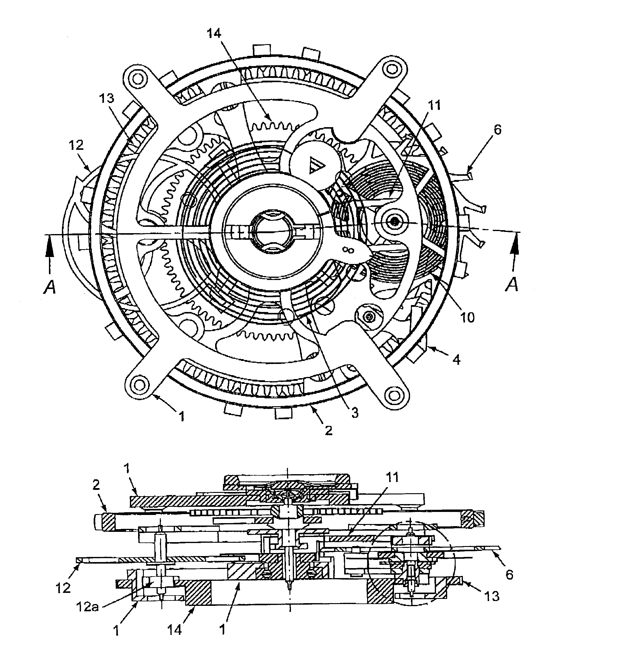
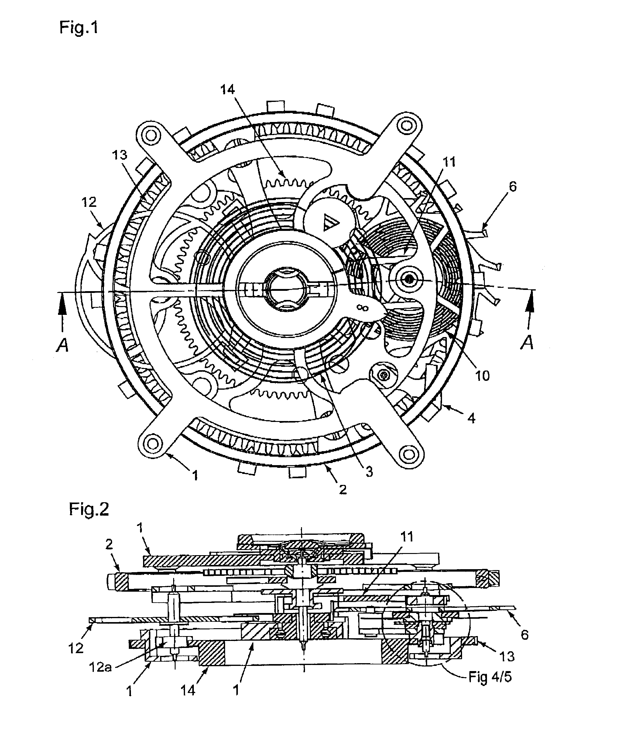
Integrated into the Tourbillon mechanism represented in FIG. 1 there is a constant-force device according to the present invention. The Tourbillon mechanism includes a Tourbillon cage 1, with a balance wheel 2 rotatably mounted in its center, a helical spring 3, a drive gear 13 as well as a fixed wheel of seconds 14 and, in certain cases, a second fixed wheel of seconds that is not shown and that is concentric to the first one, and has another number of teeth or another diameter.

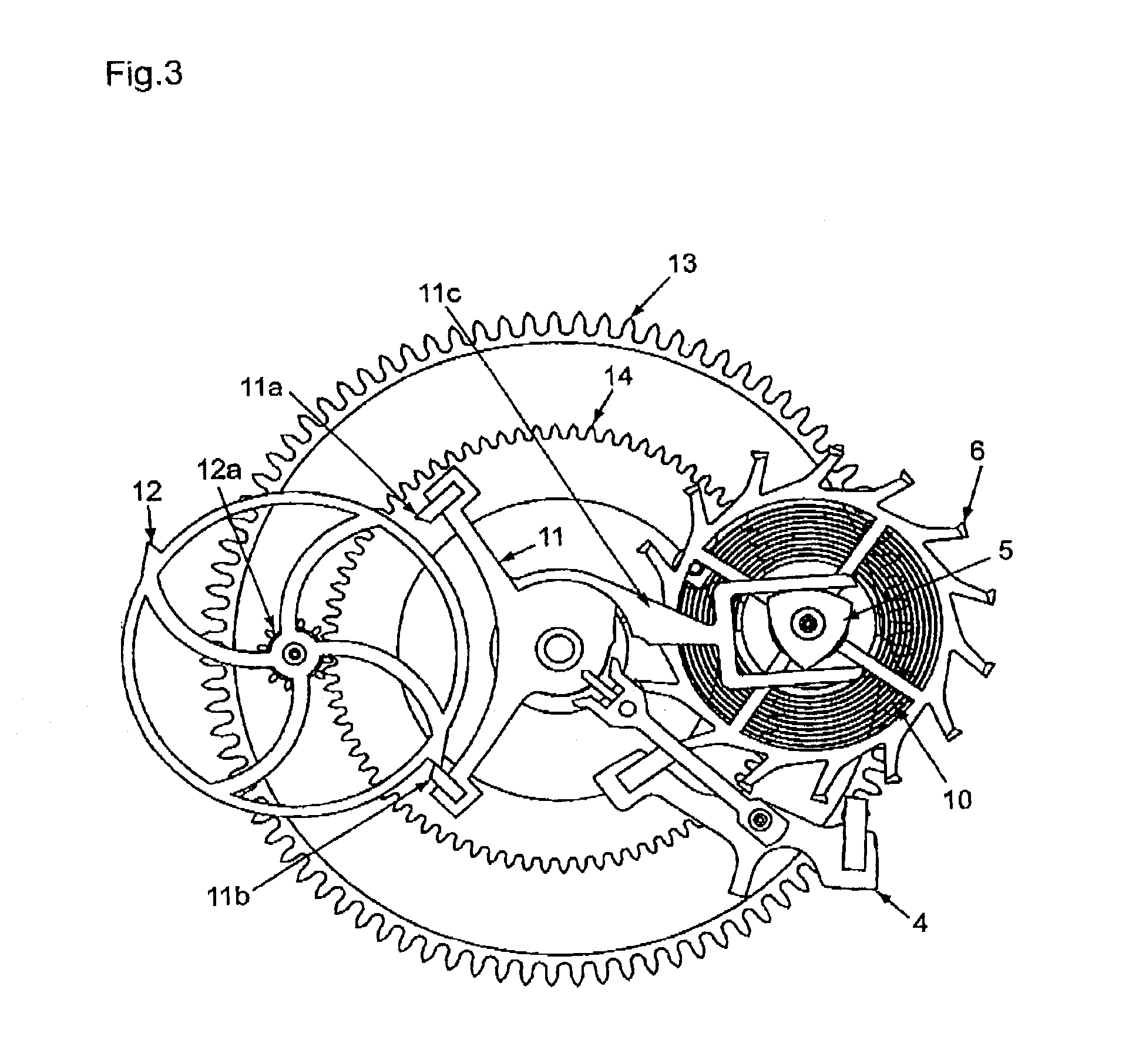
The fixed wheel of seconds 14 or, when present, the second fixed wheel of seconds is engaged with a stop wheel pinion 12a that is solidly linked with the stop wheel 12 and is mounted eccentrically and rotatably within the Tourbillon cage. In the embodiment represented here, this stop wheel 12 has two teeth cooperating with the anchor pallets 11a and 11b of a second anchor 11 o...


PUM


Abstract

A constant-force device for precise regulation of mechanical watch movements by means of a uniform transmission of force from the escape wheel to the regulating organ of the watch, this device being adapted to be integrated into a Tourbillon mechanism.

Description

BACKGROUND OF THE INVENTIONThe present invention relates to a constant-force device for the precise regulation of mechanical watch movements by the uniform transmission of force from the escape wheel to the regulating organ of the watch, this device being adapted to be integrated into a Tourbillon mechanism.DESCRIPTION OF THE RELATED ARTConstant-force devices in general have been known for quite some time, and are realized in most cases by an additional spring which, at any given point in time, has a certain amount of pre-tension compensating for the variable clockwork drive of a watch caused by fading tension of the mainspring and is periodically re-tensioned by a certain constant amount. While its tension is consumed in order to maintain the oscillations of the regulating organ of the watch, the force transmitted can be regarded as being far more constant than in the case of the regulating organ being driven solely by the mainspring.The article “Les remontoirs d'égalité et les for...

Claims


Application Information

Patent Timeline
08 Mar 2005
Publication
US6863434B2
IPC
G04B17/00; G04B15/00; G04B15/10; G04B17/28; G04B1/22
CPC
G04B17/285; G04B15/10
Inventors
MOJON, JEAN-FRAN.CEDILLA.OIS