Board-to-board connector with compliant mounting pins

a technology of mounting pins and connectors, applied in the direction of coupling device connections, coupling device details, coupling protective earth/shielding arrangements, etc., can solve the problems of increasing the size of the connector, ineffective for its intended application, and problems such as problems

Inactive Publication Date: 2005-03-08
MOLEX INC
View PDF35 Cites 74 Cited by
  • Summary
  • Abstract
  • Description
  • Claims
  • Application Information

AI Technical Summary

Benefits of technology

Still another object of the present invention is to provide terminal assemblies for a differential signal connector of the interposer type that may be easily and inexpensively manufactured.
In another important aspect of the present invention, the upper and lower housings are each coated on the exterior surfaces with a conductive coating which may be accomplished by plating the same with a conductive material. Preferably, all of the surfaces of the housings are plated and are connected to one or more ground circuits disposed on one or more circuit boards. The lower housings may include slots disposed in their portion faces that receive separately formed terminals in order to provide a series of ground connection points and to provide redundancy of connection.
In another principal aspect of the present invention and as exemplified by two different embodiments of the invention, connector assemblies of either the docking-type or the interposer-type for interconnecting a plurality of differential signal pairs between circuit boards, are provided with interstitial ground terminals disposed between certain of the differential signal pairs at the connector to circuit board interface. This interstitial ground arrangement subdivides the differential signal pairs in the connector into discrete groups, and further provides an affinity for the differential signal pairs to ground at the connector to circuit board interface to better maintain a low impedance for the high frequency differential signals thereacross.
Preferably, the upper and lower housings are each coated on the exterior surfaces with a conductive coating which may be accomplished by plating the same with a conductive material. Preferably, all of the surfaces of the housings are plated and are connected to one or more ground circuits disposed on one or more circuit boards. The lower housings may include slots, or recesses, disposed in their mounting faces that receive separately formed terminals in order to provide a plurality of ground connection points and to provide redundancy of ground connection.
The terminal assemblies are all virtually identical so that they may be inserted into any of the cavities of the housings, thereby impacting a measure of modularity to the connectors. The plug-style wafers are typically held in the receptacle connector housing, while the receptacle-style wafers are typically held in the plug connector housing. The plug-style wafers have contact blade portions in which terminals are embedded and exposed, while the receptacle-style wafers have contact blade portions that extend out from the insulative body portion and which are spread apart from each other, so that when the two connectors are mated together the receptacle-style contact blades extend into cavities of the receptacle connector and make contact with the plug-style wafer contact blades.

Problems solved by technology

However, with the use of differential signaling certain problems arise.
This approach may unduly increase the size of the connector and render it ineffective for its intended application.
Hence, if a connector requires ground terminals for each differential pair, the connector will be longer in size and possibly increase the size of the electronic components with which it is used to the extent where it is undesirable to use from a circuit board real estate perspective
Typically, there is a gap in the interface between the connector and the associated circuit board.
It is well-known that such gaps can cause undesirable discontinuities in impedance values at higher frequencies that are used in data transmission.
In such applications, the differential signal connector is interposed between the two circuit boards and the electrical connections therebetween may cause undesired levels of stress to be applied to at least some of the terminals of the connector or to the circuit boards at the connector-circuit board interface.

Method used


Image

  • Board-to-board connector with compliant mounting pins
  • Board-to-board connector with compliant mounting pins
  • Board-to-board connector with compliant mounting pins

Examples


Embodiment Construction

Connector Housing Structure

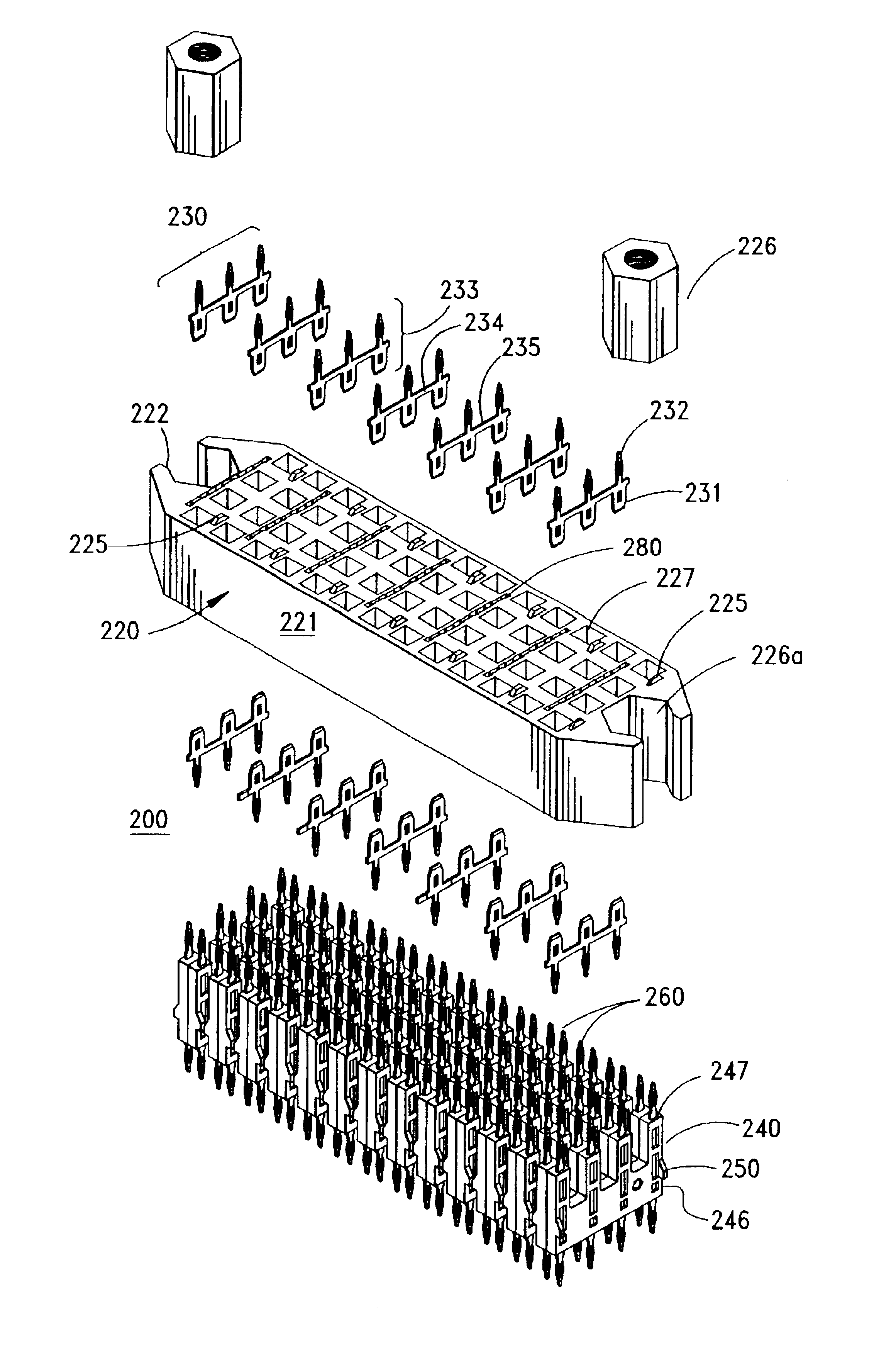
FIGS. 25A-C illustrate a pair of circuit boards 30, 31 to which are mounted a pair of connectors 40, 60. These two connectors 40, 60 are interengageable with each other so as to connect the circuits on the two circuit boards together. Of these two connectors 40 and 60, one is considered a receptacle 40 in that it is a female portion that receives a complementary and mating male plug portion 60. These two connectors 40, 60 are interengageable with each other so as to connect the circuits on the two circuit boards together. As is well-known, the two circuit boards can each carry electrical components, examples of which include but are not limited to microprocessors, memory devices but also including analog circuitry as well. Electrical components on the circuit boards are electrically coupled to conductors in the connector portions 40 and 60.

Both connectors extend partially past the edges 32, 33 so that they may be used to provide a connector that enables th...


PUM


Abstract

A connector assembly for connecting differential signal circuits on two different circuit boards has a connector housing formed from an insulative material with a conductive coating on the surfaces thereof and with cavities formed therein to receive terminal assemblies. Each internal cavity may have an elongated portion that extends transversely across the housing and a plurality of leg portions in communication with the elongated portion to define passages between opposite sides of the connector. Each cavity is suited for holding a terminal assembly having at least one pair of differential signal terminals. The terminals have opposing compliant tail portions, and interconnecting portions that are partially encapsulated by an insulative outer shell. Two shells are combined together to form a single terminal assembly. The terminal assemblies are identical in shape so that they may be inserted into any of the cavities of the housings, thereby imparting a measure of modularity to the connectors.

Description

BACKGROUND OF THE INVENTIONThe present invention relates generally to high-speed connectors, and more particularly, to connectors suitable for use in high-speed data transmission with interstitial ground arrangements between groups of differential signal pairs.In the field of data transmission, the computer and server industries attempt to constantly increase the speed at which their products can transmit and receive data. Most specifications for these type components now call for minimum speeds of 1 Gigabit per second. Such connectors typically utilize differential signaling, meaning that the signal terminals are arranged in pairs of terminals so as to take advantage of the benefits of differential signaling.However, with the use of differential signaling certain problems arise. A designer needs to bring multiple grounds into the connector in order to ensure signal isolation. A typical approach to providing the grounds in such a connector would be to utilize a single ground in each...

Claims


Application Information

Patent Timeline
Patent Type & Authority Patents(United States)
IPC IPC(8): H01R12/16H01R12/00H01R13/658H01R13/514H01R13/652H01R13/646
CPCH01R13/514H01R13/6471H01R13/6477H01R12/585H01R13/6599H01R13/65807H01R13/6587H01R23/68H01R23/7073H01R24/44H01R12/716H01R12/7064H01R12/707H01R12/727Y10S439/931H01R12/7082H01R12/73H01R12/724H01R13/6473H01R13/6594
Inventor LANG, HAROLD KEITHREGNIER, KENT E.BANAKIS, EMANUEL G.SWEENEY, KATHLEEN A.
Owner MOLEX INC
Why Eureka
Try Eureka