Protection mechanism for switch

Inactive Publication Date: 2005-03-08
YU TSUNG MOU
View PDF13 Cites 24 Cited by
  • Summary
  • Abstract
  • Description
  • Claims
  • Application Information

AI Technical Summary

Benefits of technology

The present invention will become more obvious from the following description when taken in connection with the accompan...

Problems solved by technology

The conventional circuit breaker uses a fuse between the switch and the circuit such that when there is an electrical overload, the fuse will first melt before the overload causes damages.
However, if the fuse is not properly installed or an improper fuse is used the overload current ca...

Method used


Image

  • Protection mechanism for switch
  • Protection mechanism for switch
  • Protection mechanism for switch

Examples


Embodiment Construction

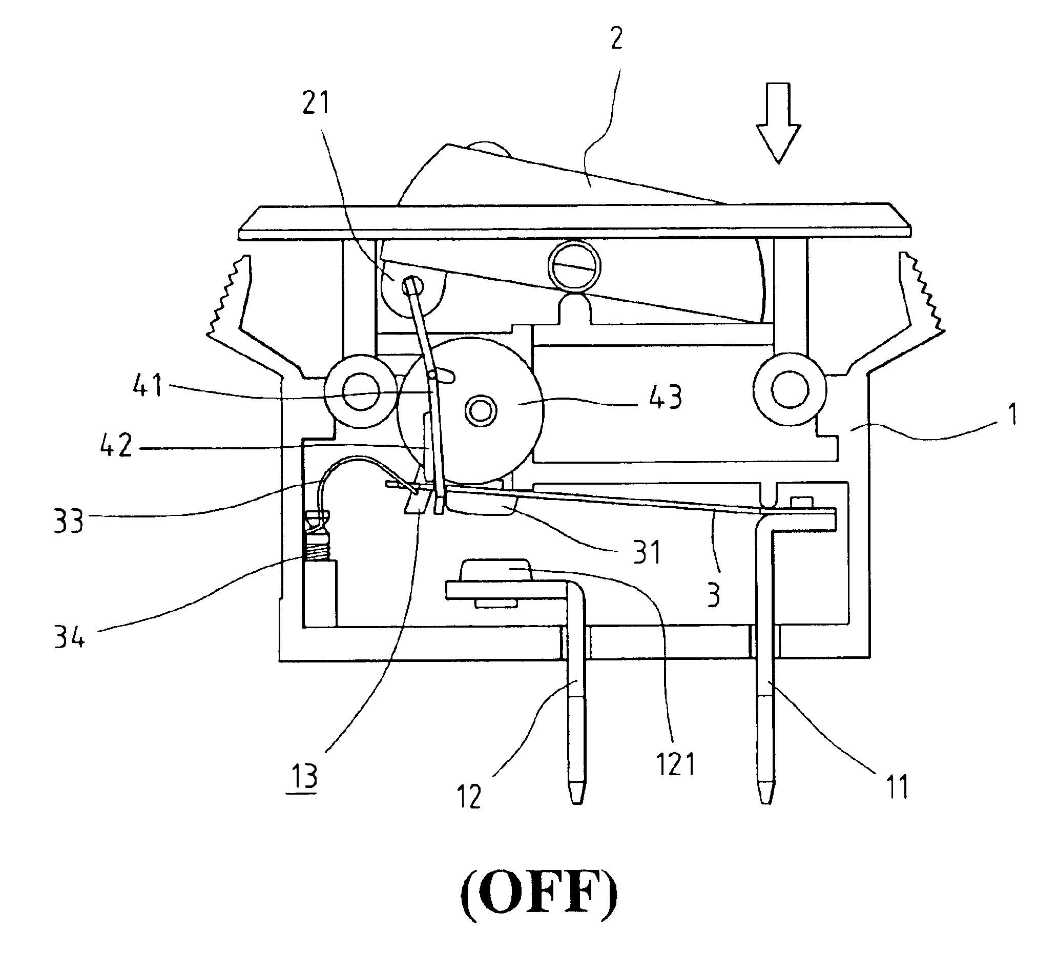
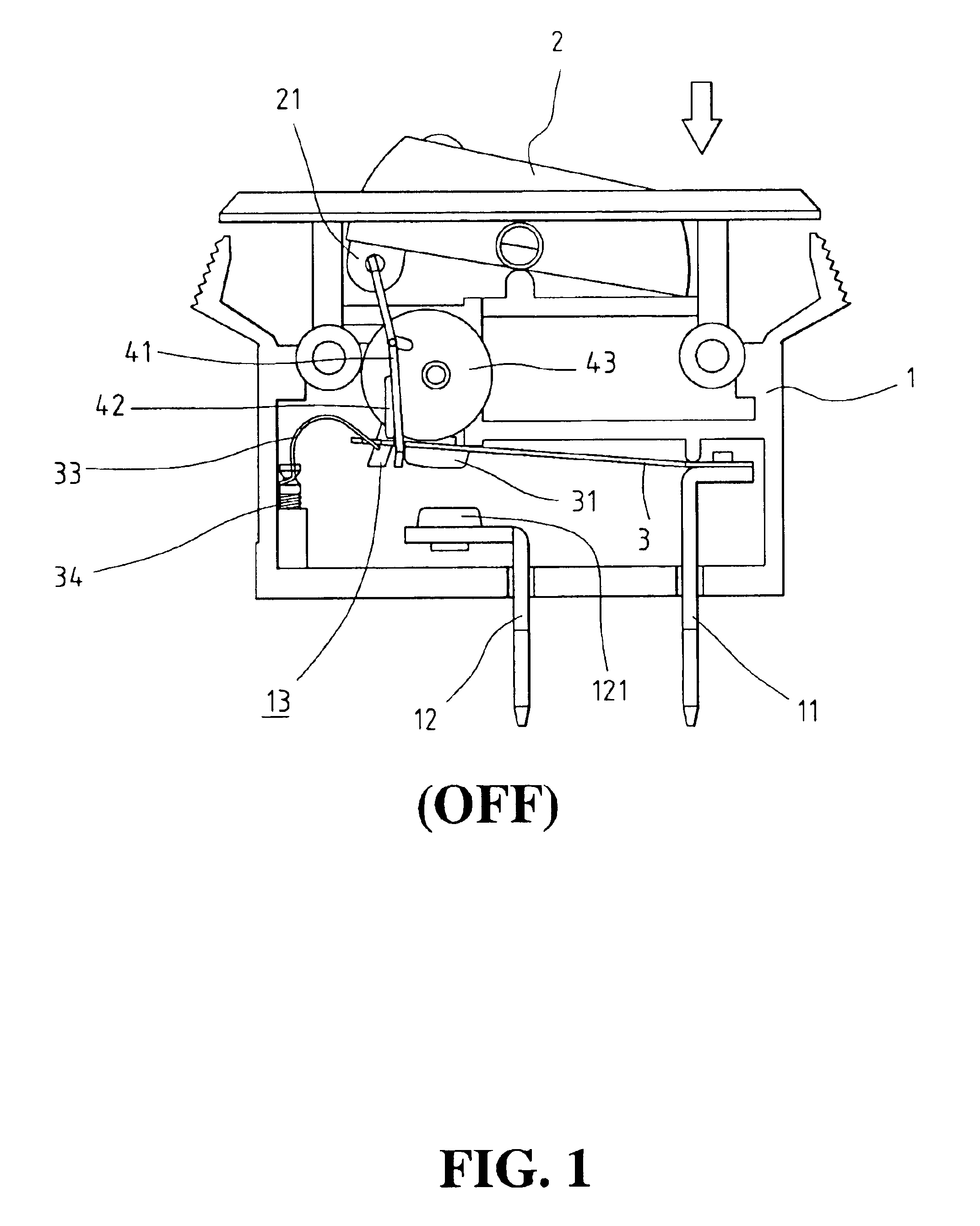
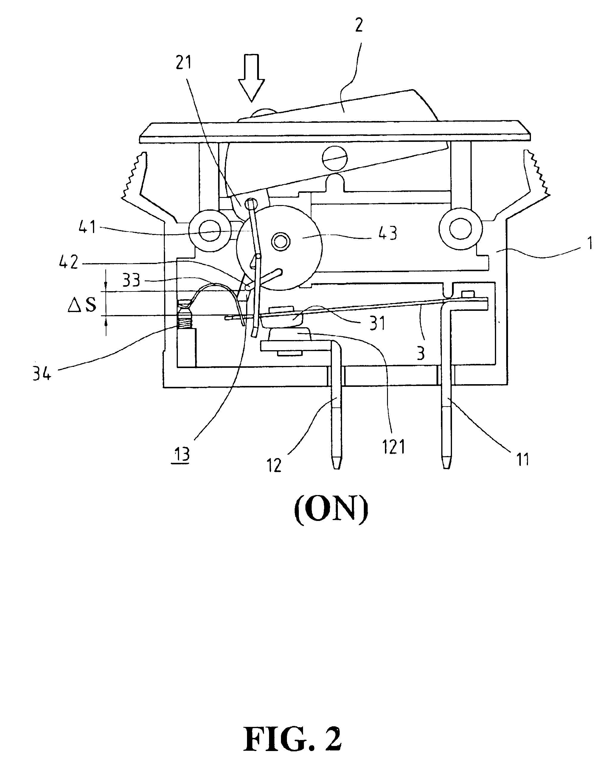
Referring to the drawings and in particular FIGS. 1, 2 and 4, a switch device comprises a case 1 having an open top and a switch member 2 is pivotably engaged with the open top of the case 1 so as to be pushed either one of two ends thereof. A connection port 21 is connected to an underside of the switch member 2 and includes a hole 22. A first terminal 11 and a second terminal 12 respectively extend through a bottom of the case 1. A bimetallic plate 3 has a first end fixed to the first terminal 11 and a first contact point 31 is connected to a second end of the bimetallic plate 3. A second contact point 121 is connected to the second terminal 12 and located beneath the first contact point 31. A groove 13 is defined in an inside thereof and a tube 14 extends from the inside of the case 1, the groove 13 oriented upward.

A block is connected to an inside of the case 1 and an adjusting bolt 34 is threadedly connected to the block. A curve flexible plate 33 has a notch 332 defined in a f...


PUM


Abstract

A protection mechanism for a switch device includes a disk rotatably connected to an inside of the case and two ends of a pull member are pivotably connected between the disk and the switch member pivotably connected to an open top of the case. One of the two ends of the pull member lifts the bimetallic plate to set the “OFF” status when pivoting the switch member. A push member has one end movably engagged with an upward groove in an inside of the case so as to push the bimetallic plate to contact one of two terminals, and the other end of the push member is pivotably connected to the disk. The push member is pivoted an angle to produce a space between the push member and the bimetallic plate when the switch member is pivoted to “ON” position and the space allows the bimetallic plate to be completely deformed when overload.

Description

FIELD OF THE INVENTIONThe present invention relates to a protection mechanism for a switch device and provides a space allowing the bimetallic plate to be completely deformed when overload.BACKGROUND OF THE INVENTIONThe conventional circuit breaker uses a fuse between the switch and the circuit such that when there is an electrical overload, the fuse will first melt before the overload causes damages. However, if the fuse is not properly installed or an improper fuse is used the overload current cannot melt the fuse and a disaster can be resulted. U.S. Pat. Nos. 5,262,748, 4,167,720, 4,937,548, 5,223,813, 5,451,729, and 5,558,211 disclose different types of circuit breakers which commonly include a complicated mechanism to drive the bimetallic plate which is expected to be deformed and bent when overload in current. Nevertheless, it is noted that the bimetallic plate does not completely deformed as desired because it is not passable to freely deformed, and is still in contact with t...

Claims


Application Information

Patent Timeline
IPC IPC(8): H01H73/26H01H73/00
CPCH01H73/26
Inventor YU, TSUNG-MOU
Owner YU TSUNG MOU
Why Eureka
Try Eureka