Facilitating automatic protection switching for provider backbone network

a backbone network and automatic protection technology, applied in data switching networks, digital transmission, instruments, etc., can solve problems such as path failure, and achieve the effect of enhancing the protection switching mechanism and enhancing the existing protection switching mechanism

Inactive Publication Date: 2008-11-13
RPX CLEARINGHOUSE
View PDF15 Cites 44 Cited by
  • Summary
  • Abstract
  • Description
  • Claims
  • Application Information

AI Technical Summary

Benefits of technology

[0006]An existing protection switching mechanism is enhanced through an extension to the automatic protection switching protocol data unit (APS PDU). Alternatively, an existing protection switching mechanism is enhanced by encapsulating the existing APS PDU with an I-SID that permits the receiving end point bridge to differentiate such an encapsulated APS PDU from data frames belonging to customer flows being transported. In conjunction with transmitting Et

Problems solved by technology

When one end point bridge stops receiving CCMs from the other end point bridge alo

Method used


Image

  • Facilitating automatic protection switching for provider backbone network
  • Facilitating automatic protection switching for provider backbone network
  • Facilitating automatic protection switching for provider backbone network

Examples


Embodiment Construction

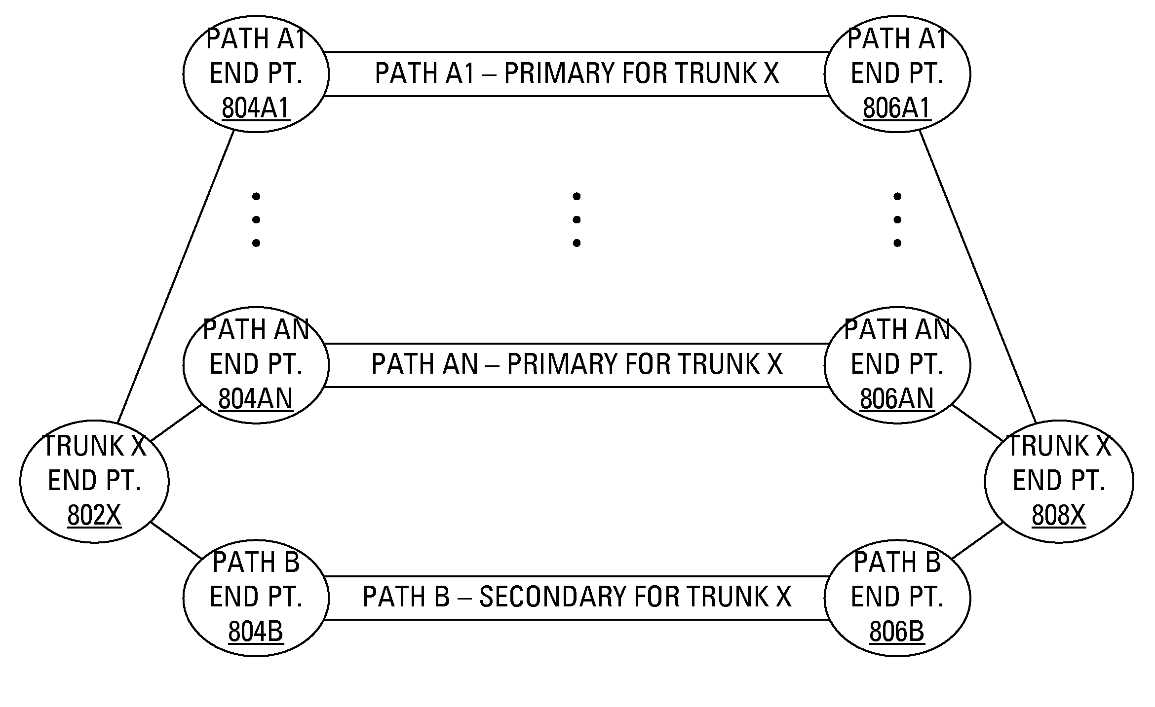
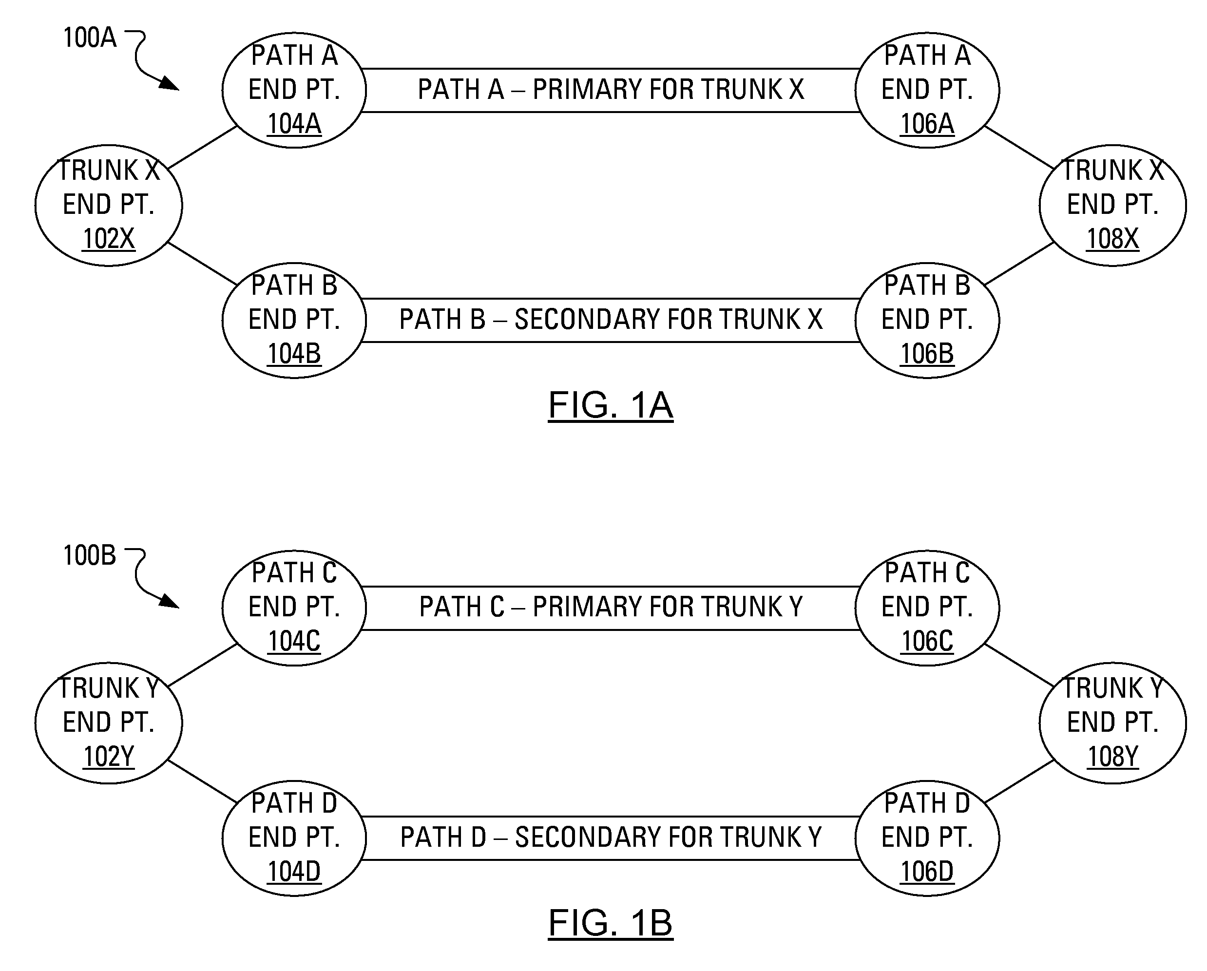
[0024]FIG. 1A illustrates a network 100A having two identified paths: a path A, extending between a first path A end point 104A and a second path A end point 106A; and a path B, extending between a first path B end point 104B and a second path B end point 106B. The paths A and B may be used in a protection switching mechanism for a connection (called “trunk X”) between a first trunk X end point 102X and a second trunk X end point 108X. In particular, in operation, path A may be designated as the primary path for trunk X and path B may be designated as the secondary path for trunk X.

[0025]The end points 102X, 104A, 104B, 106A, 106B and 108X, indeed all the end points used in networks described herein, are expected to physically or virtually have components typical in such networks. That is, a generic bridge comprising end points 102X, 104A, 104B or 106A, 106B, 108X has at least one input port, at least one output port, a processor for directing traffic between the input and the outpu...


PUM


Abstract

An existing protection mechanism is enhanced through the use of an automatic protection switching protocol data unit (APS PDU). In conjunction with transmitting Ethernet frames to a second bridge over a primary path, a first bridge transmits APS PDUs to the second bridge over a secondary path. The APS PDUs provide the second bridge with information about the protection switching mechanism being used and provide indications regarding the status of the primary path. In particular, protection switching may be facilitated by forming an APS PDU that is extended to include an indication of an identity for a trunk or a primary path before transmitting the APS PDU to the second bridge. Alternatively, after forming a regular APS PDU, protection switching may be facilitated by encapsulating the regular APS PDU with information identifying a trunk or a primary path before transmitting the APS PDU to the second bridge.

Description

CROSS REFERENCE TO RELATED APPLICATIONS[0001]The present application claims priority to U.S. Provisional Patent Application Ser. No. 60 / 917,124, filed May 10, 2007, the contents of which are hereby incorporated herein by reference.FIELD OF THE INVENTION[0002]The present application relates generally to protection switching and, more specifically, to facilitating automatic protection switching for a Provider Backbone network.BACKGROUND OF THE INVENTION[0003]Provider Backbone Transport (PBT) offers a mechanism to permit scalable point-to-point tunnels to be configured or signaled in an Ethernet subnetwork. Advantageously, PBT provides a set of enhancements to Ethernet technology that allow use of Ethernet in a carrier class transport network. PBT uses concepts of Virtual Local Area Network (VLAN) tagging as provided in the Institute for Electrical and Electronics Engineers (IEEE) standard 802.1Q, stacked VLANs as provided in the IEEE standard 802.1ad and Provider Backbone Bridges as p...

Claims


Application Information

Patent Timeline
IPC IPC(8): G06F15/16H04L69/40H04L45/24H04L45/28
CPCH04L12/4658H04L12/4662H04L45/22H04L45/28H04L69/40
Inventor SKALECKI, DAREKCIVIL, GERALDINEMOHAN, DINESH
Owner RPX CLEARINGHOUSE
Why Eureka
Try Eureka