Method and apparatus for controlling light emitting diodes

a technology of light-emitting diodes and control methods, which is applied in the direction of electric variable regulation, process and machine control, instruments, etc., can solve the problems of adding to the total circuit power dissipation, difficult to maintain a precise and uniform level of current in each led, and difficult to achieve uniform current from led to led in most circuits

Inactive Publication Date: 2005-03-08
VISTEON GLOBAL TECH INC
View PDF13 Cites 236 Cited by
  • Summary
  • Abstract
  • Description
  • Claims
  • Application Information

AI Technical Summary

Benefits of technology

The LED circuit may offer one or more advantages over other technologies (such as fluorescent lamps) in terms of costs, performance, c

Problems solved by technology

However, uniformity of current from LED to LED can be difficult to achieve in most circuits because of variations in supply and LED voltages and circuit impedances.
However, it is difficult to maintain a precise and uniform level of current in each of the LEDs because of variations in supply and LED voltages and cir

Method used


Image

  • Method and apparatus for controlling light emitting diodes
  • Method and apparatus for controlling light emitting diodes
  • Method and apparatus for controlling light emitting diodes

Examples


Embodiment Construction

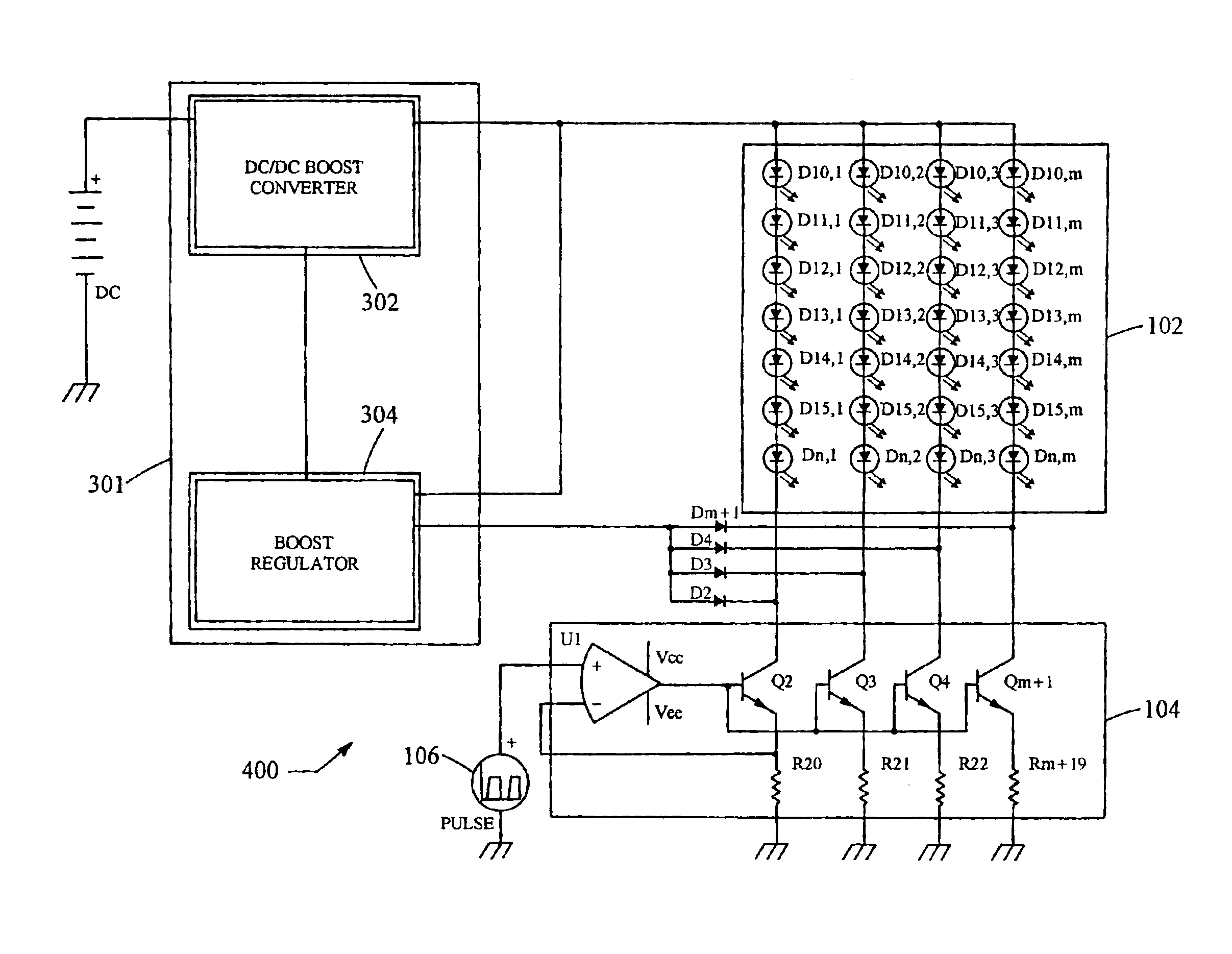
The following discussion presents a light emitting diode circuit for controlling a plurality of light emitting diodes (“LEDs”). The circuit maximizes uniformity of current in the LEDs, dimming range, and efficiency, while minimizing costs, power dissipation, and electromagnetic interference (“EMI”).

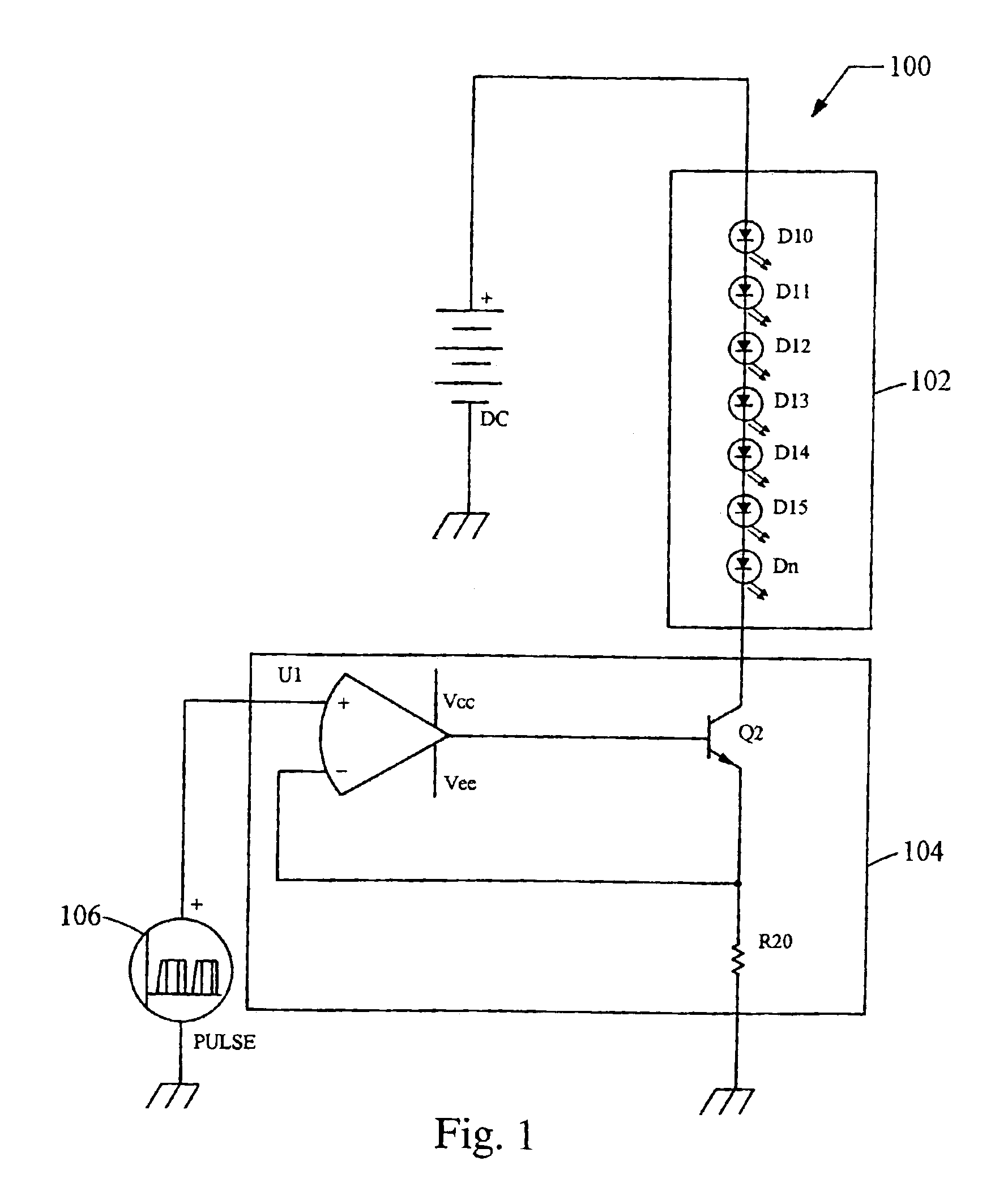
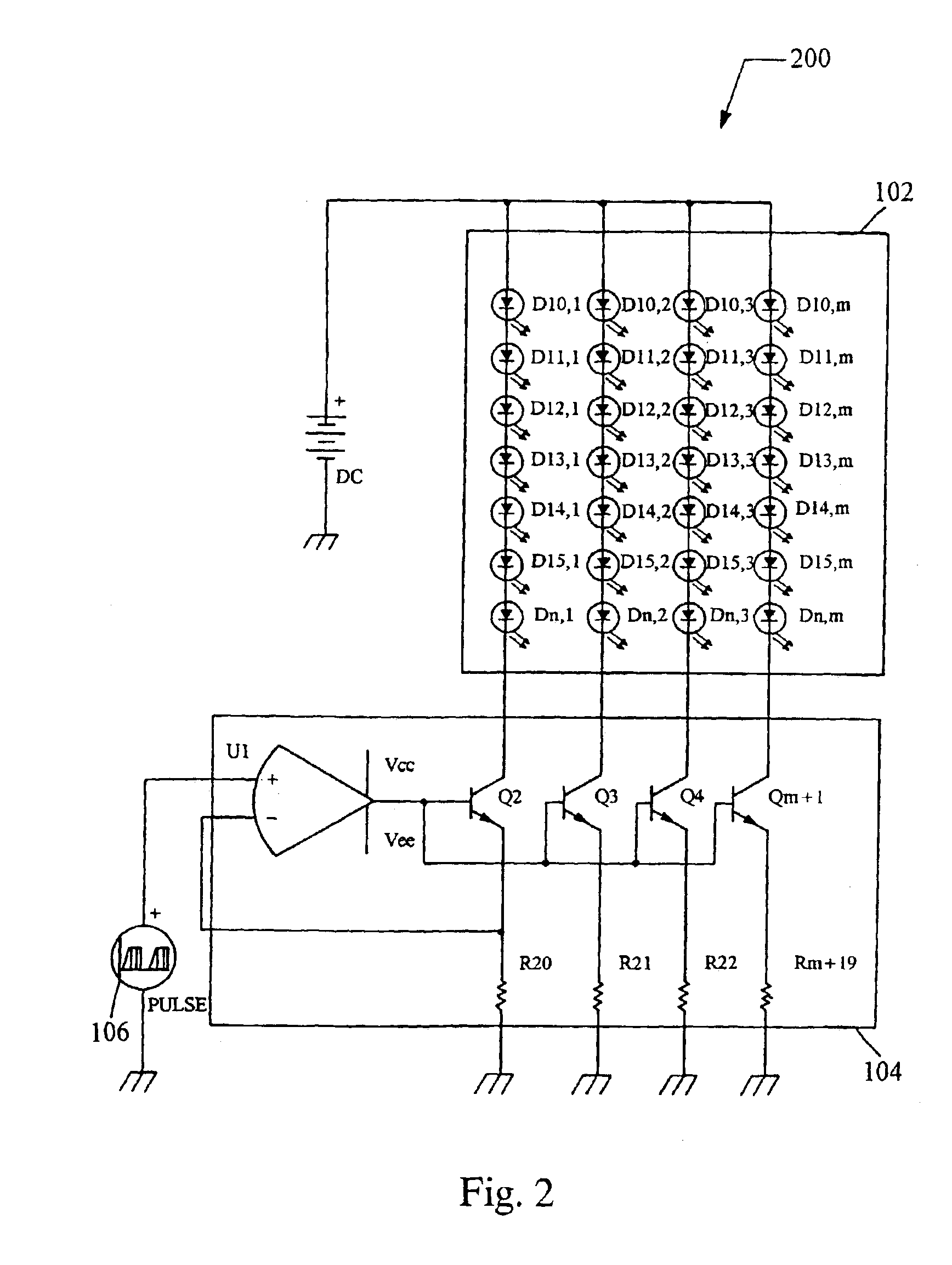
Although the invention is generally directed to an LED circuit with a hybrid parallel-series configuration, for purposes of illustration, the discussion begins with FIG. 1 illustrating a basic LED circuit 100. The LED circuit 100 includes a fixed voltage source DC, for example, a supply of 15 volts, connected in series with an array of LEDs 102 and a current regulating circuit 104. The fixed voltage source DC is dimensioned in accordance with the expected highest LED chain voltage to maintain the required current conduction though the LEDs. With a fixed voltage supply, the current regulating circuit 104 is dimensioned for power according to the expected lowest LED chain voltage and highes...


PUM


Abstract

A light emitting code (“LED”) circuit includes a plurality of light emitting diodes connected in a hybrid parallel-series configuration, and a current regulating circuit that includes a current regulating element connected to a first chain of the plurality of chains of LEDS, and a plurality of current mirroring elements, each current mirroring element being connected to a respective chain of the plurality of chains of LEDs.

Description

BACKGROUND1. Technical FieldThe present invention relates generally to light emitting diodes, and more particularly relates to controlling a plurality of light emitting diodes.2. Background InformationLight emitting diodes (“LEDs”) are becoming increasingly popular as light source devices, especially as their cost continues to decrease. Typical applications for LEDs in automobiles include illumination of information display devices, such as liquid crystal diode displays, and illumination of gauges in instrument panel assemblies.Typical applications utilize a plurality of LEDs to produce the required total light intensity. In general, the LEDs have a light intensity output that is adjustable over a wide range from full intensity to some small fraction of the full intensity, for example, {fraction (1 / 100)} of the full intensity, in response to an operator or microcomputer command. The range of operating light intensity is commonly referred to as a dimming range or dimming ratio over w...

Claims


Application Information

Patent Timeline
IPC IPC(8): H05B33/02H05B33/08H01L33/00H05B44/00
CPCH05B33/0815H05B33/0827H05B33/0818Y02B20/347H05B45/46Y02B20/30H05B45/38
Inventor DYGERT, GREGORY J.
Owner VISTEON GLOBAL TECH INC
Why Eureka
Try Eureka