Method and system for measuring fly height

a technology of fly height and measurement method, applied in the direction of maintaining head carrier alignment, digital recording, instruments, etc., can solve the problem of pushing past the limits of this measurement techniqu

Inactive Publication Date: 2005-03-08
SEAGATE TECH LLC
View PDF14 Cites 49 Cited by
  • Summary
  • Abstract
  • Description
  • Claims
  • Application Information

AI Technical Summary

Problems solved by technology

While this technique is sufficiently precise for the current generation of products, the need to measure fly heights to accuracies of a fraction of a wavelength of light threatens to push pa

Method used


Image

  • Method and system for measuring fly height
  • Method and system for measuring fly height
  • Method and system for measuring fly height

Examples


Embodiment Construction

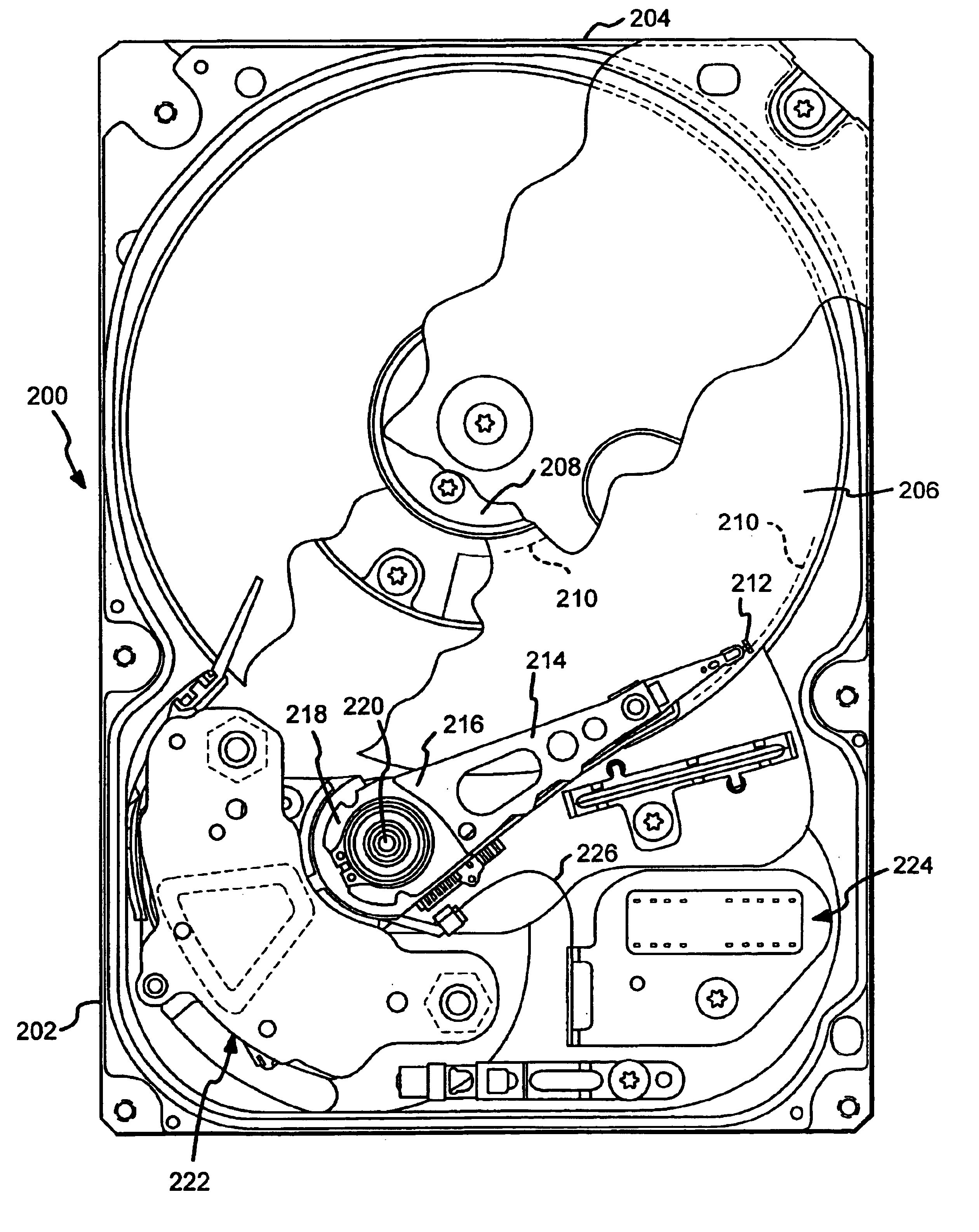
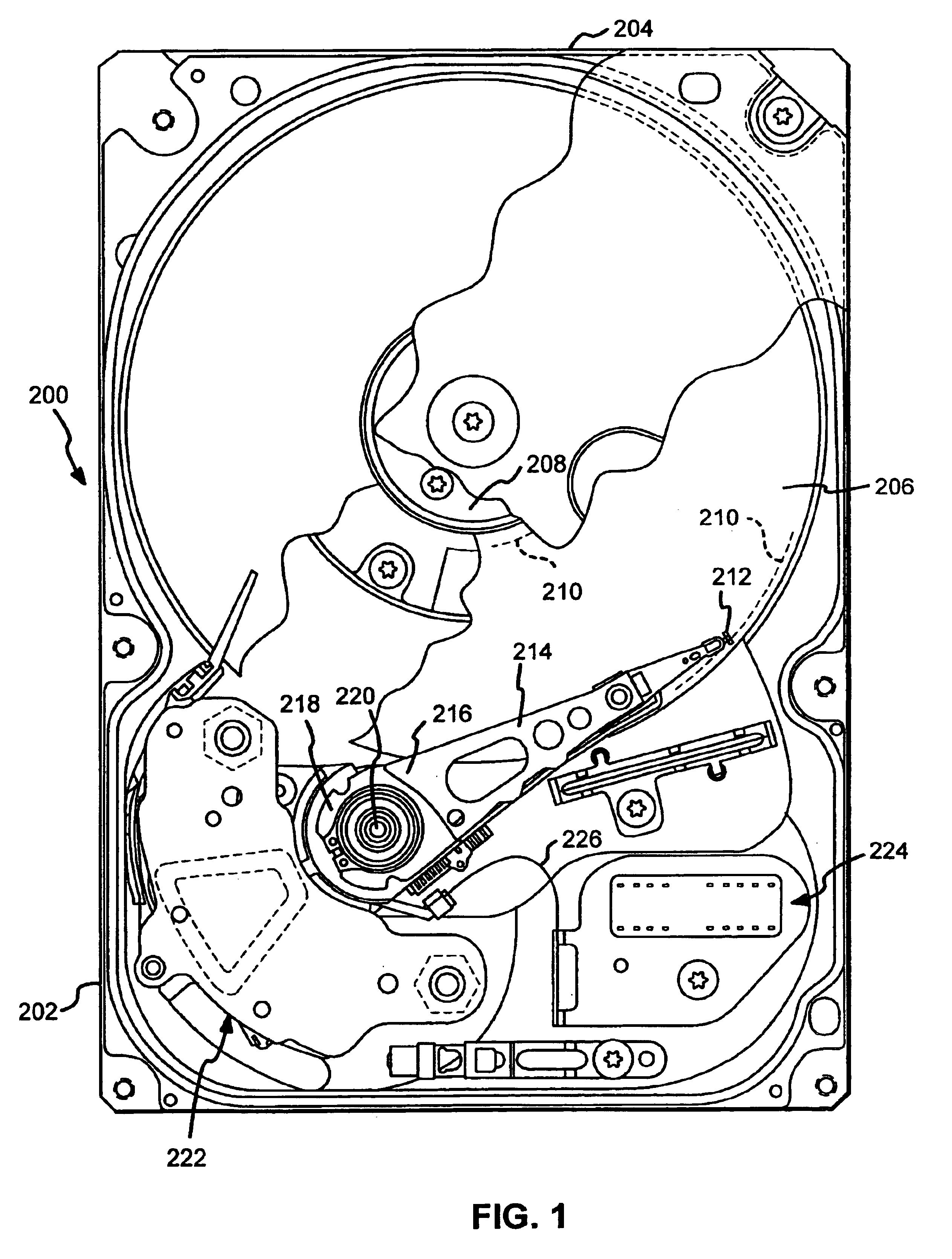
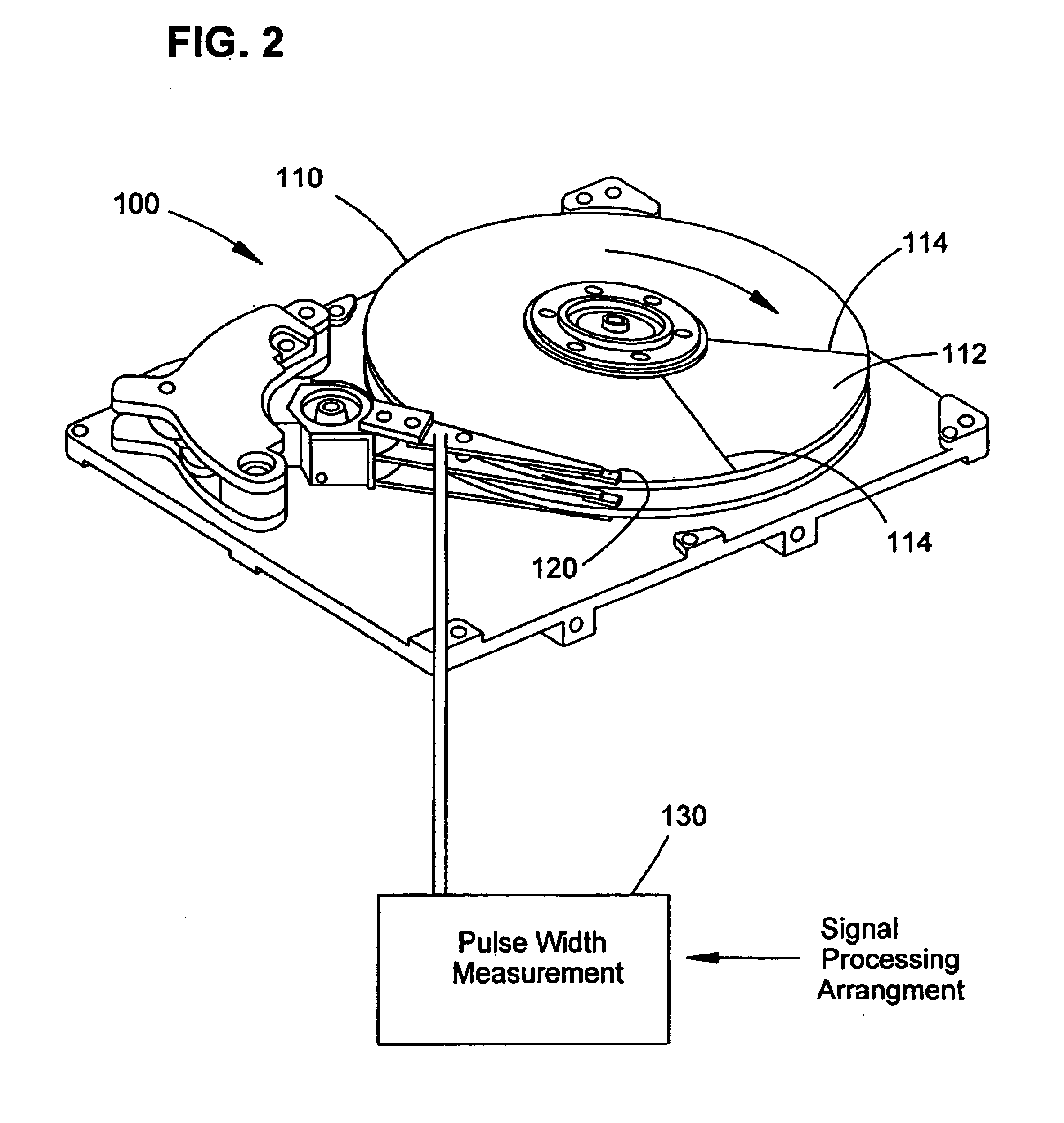
Turning now to the drawings, and specifically to FIG. 2, shown is a plan view of a disc drive 200 that can incorporate an example embodiment of the present invention. The disc drive 200 includes a base 202 to which all other components are directly or indirectly mounted and a top cover 204 (shown in partial cutaway) which, together with the base 202, forms a disc drive housing which encloses internal components and isolates these components of the disc drive 200 from external contaminants.

The disc drive 200 includes one or more discs 206 which are mounted for rotation on a spindle motor shown generally at 208. The discs 206 include on their surfaces a plurality of circular, concentric data tracks, the innermost and outermost of which are shown by dashed lines at 210, on which data are recorded via an array of vertically aligned head assemblies 212. The head assemblies 212 are supported by head suspensions, or flexures 214, which are attached to actuator arms 216. The actuator arms 2...


PUM


Abstract

A system and method for measuring the fly height of a head flying over a disc in a disc drive is disclosed. A head is vertically spaced from a rotating disc surface by an air bearing surface. The disc has one or more radial grooves in the surface of the disc. As the disc rotates, the radial grooves on the disc pass under the head and induce a perturbation in the signal. By measuring the perturbations in the signal caused by the grooves in the disc surface, and by processing the measurement signal, a vertical spacing signal proportional to the vertical spacing between the disc and the head can be obtained.

Description

FIELD OF THE INVENTIONThis invention relates generally to the field of data storage devices, and more particularly, but not by way of limitation, to a new system and method for measuring fly height between a head and a data storage surface.BACKGROUND OF THE INVENTIONThe invention relates to direct access data storage devices such as magnetic disc storage devices. In a magnetic disc storage device, a magnetic data storage disc spins at a high speed while a transducer (or head) is suspended slightly above the disc surface. The transducer flies above the disc surface on an air bearing. The transducer typically includes a magnetoresistive read element and an inductive write element on the slider, commonly called the head. The head writes information onto the disc in concentric circular tracks. Different tracks are accessed for writing or reading by changing the radial position of the recording head so as to position the head above the desired track.One of the most important parameters i...

Claims


Application Information

Patent Timeline
IPC IPC(8): G11B27/36G11B5/60
CPCG11B5/6005G11B5/6029G11B27/36G11B2220/20
Inventor FAYEULLE, SERGE JACQUESSMITH, PAUL W.
Owner SEAGATE TECH LLC
Why Eureka
Try Eureka