

Illumination system for escalator handrails
a technology of illumination system and escalator, which is applied in the direction of elevators, conveyors, escalators, etc., can solve the problem that monochromatic handrails are difficult for some people to s
- Summary
- Abstract
- Description
- Claims
- Application Information
AI Technical Summary
Benefits of technology
Problems solved by technology
Method used
Image

Examples
second embodiment
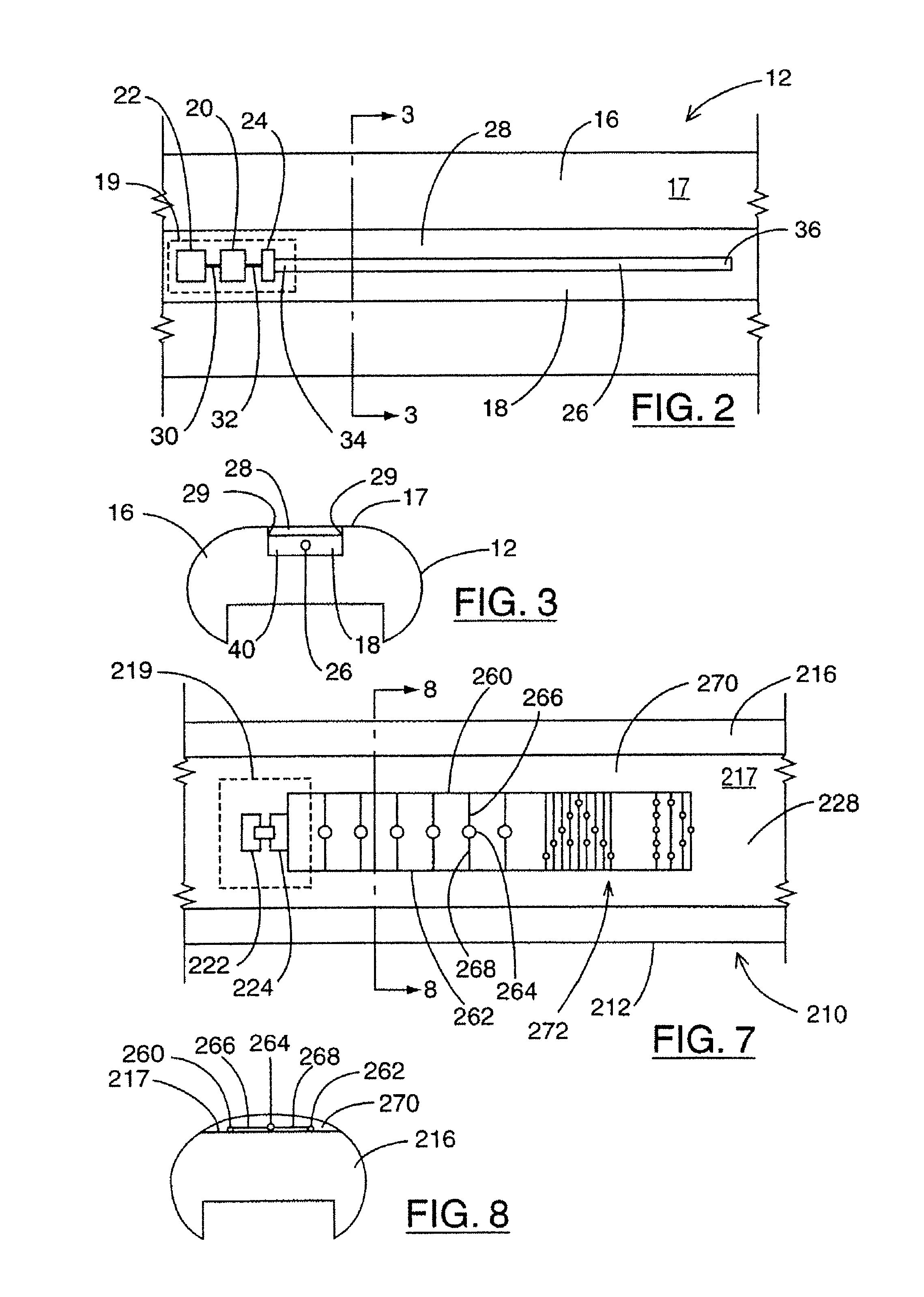
Reference is next made to FIGS. 5 and 6 which illustrate an escalator handrail 112 which is part of a second illumination system 111 according to the present invention. Illumination system 111 includes charging stations 138 (not shown) which are identical to charging stations 38. Elements of escalator handrail 112 which correspond to escalator handrail 12 are given the same reference numerals increased by 100. As is known, the movement of an escalator handrail is generally controlled by mechanical devices such as pinch rollers and motors which can exert substantial forces on the handrail. If in a particular embodiment of an escalator handrail according to the present invention, such pinch rollers and other mechanical devices would exert too great a mechanical compression force so as to cause cover 28, optic fiber or power / light block 19 to become damaged, then protective elements may be installed in cavity 40.
Escalator handrail 112 is identical to escalator handrail 12 except for th...
third embodiment
Reference is next made to FIG. 7 which illustrates a handrail 212 which is part of an illumination system 211 according to the present invention. Illumination system 211 includes charging stations 238 (not shown) which are identical to charging stations 38. Elements of handrail 212 which correspond to elements of handrail 12 are given similar reference numerals increased by 200. Handrail 212 comprises a base 216, a power block 219, power rails 260 and 262 and a plurality of light sources 264 and a cover 270.
Base 216 does not have a channel like channel 18 of handrail 12. Power block 219 comprises a charging circuit 222 and a power source 224, which operate in the same manner as charging circuit 22 and power source 24. Charging circuit 222 receives power from charging stations (not shown) identical to charging station 38. Charging circuit 222 and power source 224 are mounted on the top 217 of base 216. Power source 224 is coupled to power rail 260 and 262 which respectively carry pos...
fourth embodiment
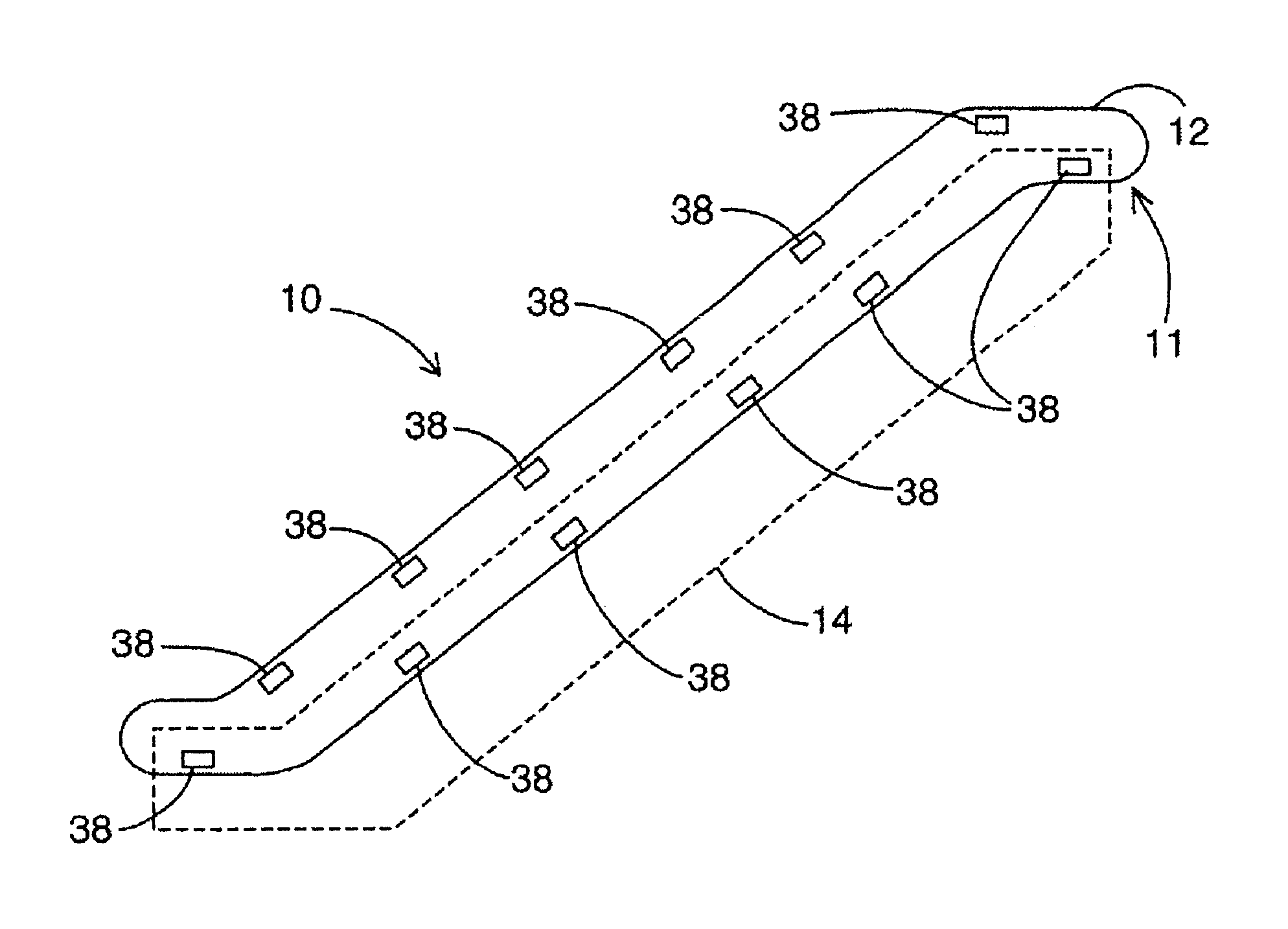
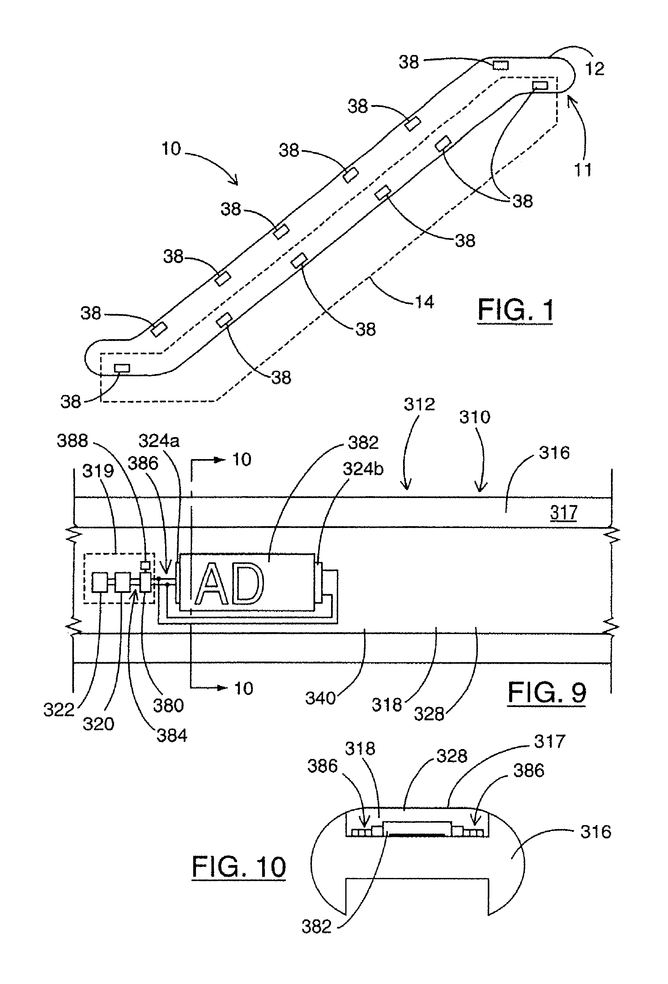
Reference is next made to FIG. 9, which illustrates a handrail 312 which is part of an illumination system 311 according to the present invention. Illumination system 311 includes charging stations 338 (not shown) which may be identical to charging stations 38. Elements of handrail 312 which correspond to elements of handrail 12 are given similar reference numerals increased by 300. Handrail 312 comprises a base 316, a power / lighting control block 319 and a display board 382. Power / lighting control block 319 includes power source 320, charging circuit 322, a pair of light sources 324a and 324b, a microcontroller 380 and a position detector 388. Microcontroller 380 is coupled to power source 320 through a coupling 384, which may be one or more wires, to receive power and is coupled to light sources 324a and 324b through coupling 386, which may be one or more wires, to control their operation. Microcontroller 380 is coupled to position detector 388 through a coupling 390, which may be...
PUM
 Abstract
Description
Claims
Application Information