Optical connector with shutter

Inactive Publication Date: 2005-03-15
FUJIKURA LTD
View PDF1 Cites 50 Cited by
  • Summary
  • Abstract
  • Description
  • Claims
  • Application Information

AI Technical Summary

Benefits of technology

In the optical connector with a shutter of the present invention, a shutter unit that blocks emitted light from the connected optical connector is incorporated into the connector housing such that the optical connector and connected optical connector are connected inside a connector hole into which the optical connector is inserted and connected. The shutter unit comprises a body installed in proximity to the position of the connection between the optical connector in the connector hole and the connected optical connector, and tongue-shaped shutter pieces that project from the body into the connector hole and are disposed so as to be able to block the emitted light fr

Problems solved by technology

1. Many require a manual opening and closing operation during insertion of the optical connector, and considerable labor is involved in this operation.
2. The structure for installing the optical connector so as to be freely opened and closed is complex, many are formed by a number of parts, and the cost becomes high. In addition, downsizing is difficult, and large-scale design changes and enlargement of the optical connector adaptor becomes necessary.
3. Because downsizing as described in 2 above is difficult, it cannot be applied to using multiple cores in the optical connector adaptor, increasing the density of the connector installation hole, or downsizing.
Although, for example, installing an electrically conducting cover on the outside of the optical connector

Method used


Image

  • Optical connector with shutter
  • Optical connector with shutter
  • Optical connector with shutter

Examples


Example

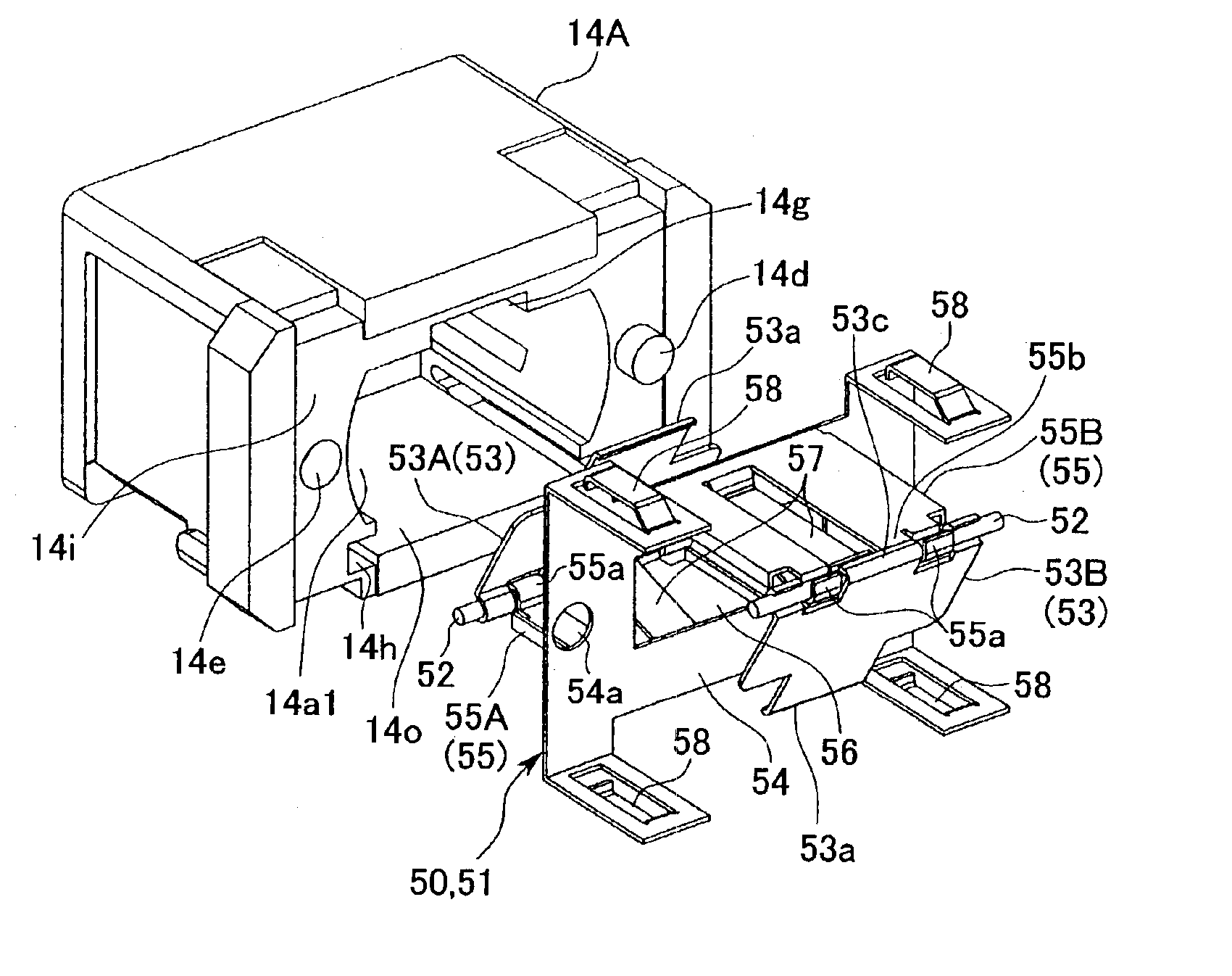
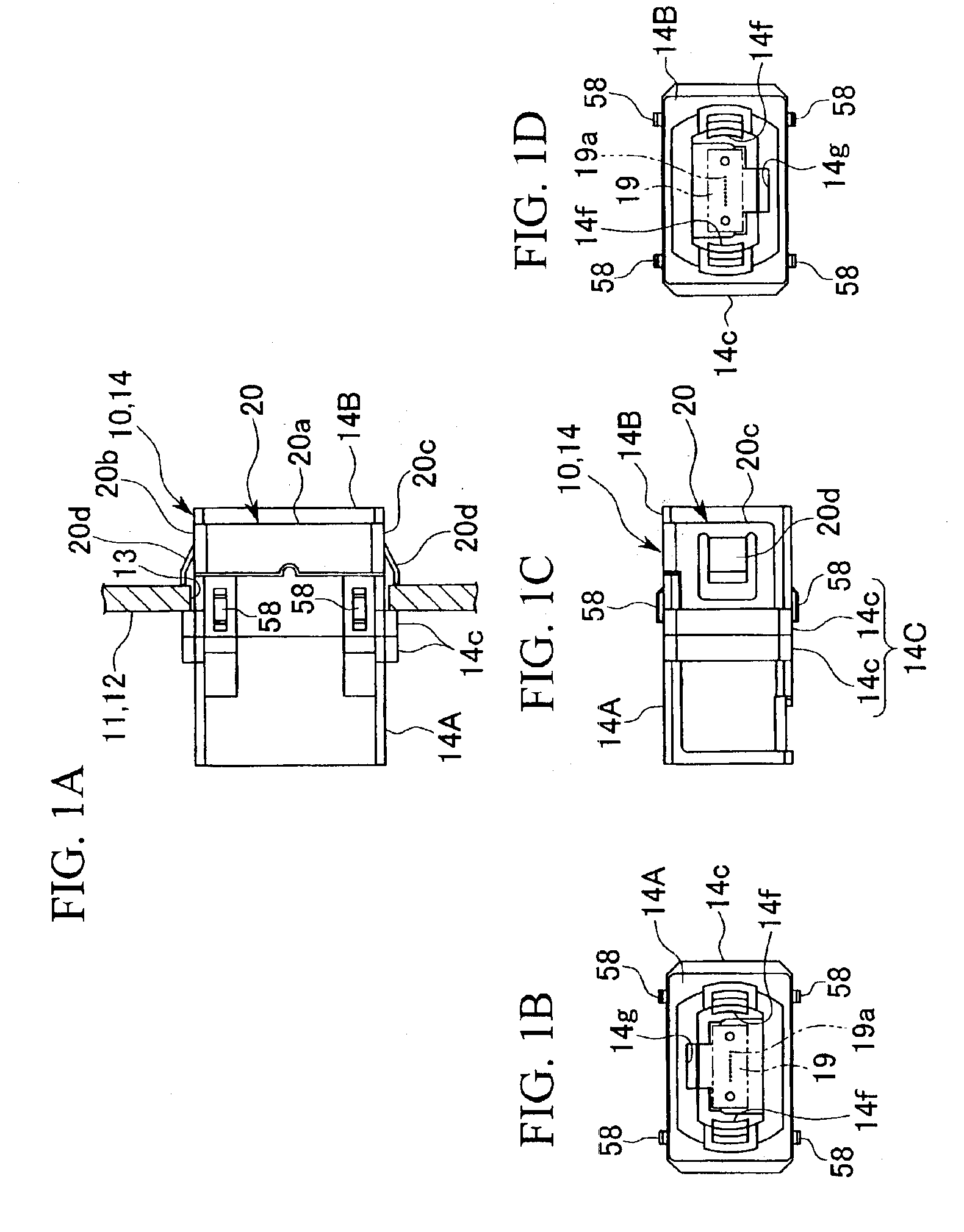
The embodiments of the present invention will be explained in the following with reference to the figures. FIGS. 1A to 1D show the exterior of the optical connector 10 with a shutter in an embodiment of the present invention; FIG. 2 is a cross sectional drawing showing the installed state of the optical connector 10 with a shutter with respect to the installation wall 12 of the casing 11 of an instrument, and shows the vicinity of the connector installation hole 13 that has been opened in the installation wall 12; FIG. 3 is a perspective drawing viewing the installation state of the installation wall 12 of the optical connector 10 with a shutter shown in FIG. 2 from the outside of the casing 11; FIG. 4 is a perspective drawing showing the connector installation hole 13 formed in the installation wall 12; FIG. 5 is a perspective drawing viewing the installation state of the installation wall 12 of the optical connector 10 with a shutter shown in FIG. 2 from inside the casing 11; FIG....


PUM


Abstract

This optical connector with a shutter is for blocking emitted light from the connected optical connector, such as an optical connector adaptor, provided in a connector hole of a connector housing by using a shutter. In this optical connector with a shutter, the shutter unit is assembled in the center part of the connector housing, and the emitted light in the connector hole from the connected optical connector is blocked by shutter pieces of the shutter unit. Furthermore, an electromagnetic shielding capacity can be obtained without enlarging the optical connector by making the shutter unit from electrically conducting members.

Description

BACKGROUND OF THE INVENTION1. Field of the InventionThe present invention relates to an optical connector, and in particular to an optical connector with a shutter that blocks the emitted light from the connected optical connector and is provided in the connector housing into which the optical connector is inserted and connected.2. Description of the Related ArtAs shown in FIG. 17, for example, in the case that the optical connector 3 (optical connector plug) is inserted into the connector hole 2 of the optical connector adaptor 1 and connected to the optical connector 4 (optical connector plug; below referred to as the “adaptor side optical connector”) that has been inserted from the opposite side and connected to the optical connector adaptor 1, it is necessary to prevent the emitted light H from the distal end of the adaptor side optical connector 4 from entering the eyes of the worker who is manipulating the optical connector 3 on the insertion side. The same requirement is pres...

Claims


Application Information

Patent Timeline
IPC IPC(8): G02B6/38G02B6/42G02B6/36
CPCG02B6/3825G02B6/3849G02B6/3897G02B6/4277G02B6/3885G02B2006/4297G02B6/3893
Inventor TANAKA, YUWAFUJIWARA, KUNIHIKOISHIKAWA, TAKAAKI
Owner FUJIKURA LTD
Why Eureka
Try Eureka