Multi-function machine tool and machining method in multi-function machine tool

a multi-functional machine tool and machining method technology, applied in the direction of manufacturing tools, gear teeth, instruments, etc., can solve the problems of arbitrary setting of the groove width, the arbitrary setting of the groove radius (the rotating radius of the tool), the difficulty of machining, and the lik

Inactive Publication Date: 2005-03-15
MORI SEIKI HITECH
View PDF8 Cites 21 Cited by
  • Summary
  • Abstract
  • Description
  • Claims
  • Application Information

AI Technical Summary

Benefits of technology

Accordingly, the present invention relates to a multi-function machine tool which makes it possible to machine helical grooves of diverse shapes in a workpiece using an all-purpose multi-function machine tool, and a machining method in this multi-function machine tool.
Furthermore, in the abovementioned multi-function machine tool, it is desirable that the abovementioned workpiece attachment means can attach the abovementioned workpiece in a position that is separated by a specified distance from the abovementioned main spindle toward the front on the axial line of the abovementioned main spindle, and that the machine tool be devised so that when the abovementioned turning tool rest is caused to perform a turning motion about an arbitrary position that differs from the position of the above-mentioned turning axis by concurrently and synchronously performing a turning motion of the abovementioned turning tool rest about the abovementioned turning axis and a circular-arc motion based on the relative motion of the abovementioned tool rest main body in the abovementioned first linear direction and the abovementioned second linear direction, there is no interference between the abovementioned turning tool rest and splash guards which are disposed on the abovementioned bed, and which are devised so that splashing material generated inside the machining region does not splash to the outside of the machining region, or between the turning tool rest and the abovementioned bed itself.
Furthermore, the machining method of the multi-function machine tool of the present invention is a machining method in a multi-function machine tool comprising a main spindle which is rotatably disposed on the bed of the machine tool, and which has workpiece attachment means for attaching a workpiece on the tip end thereof, a tool rest main body which is disposed movably in relative terms in a first linear direction parallel to the axial line of the abovementioned main spindle, and in a second linear direction perpendicular to the abovementioned first linear direction, and a turning tool rest which is disposed on the abovementioned tool rest main body, allows the mounting of a tool, and is disposed so that this tool rest can turn relative to the abovementioned tool rest main body about a turning axis which has an axial line oriented in a direction that is perpendicular to both the abovementioned first linear direction and the above-mentioned second linear direction, this machining method comprising the steps of setting the center position of the turning motion that the abovementioned tool mounted on the above-mentioned turning tool rest is caused to perform in an arbitrary position that differs from the position of the above-mentioned turning axis, determining the circular-arc motion based on the relative motion of the abovementioned tool rest main body in the abovementioned first linear direction and the abovementioned second linear direction that is necessary in order to cause the abovementioned tool to perform the abovementioned turning motion, and performing the machining of the abovementioned workpiece by causing the above-mentioned turning tool rest to perform a turning motion about the abovementioned turning axis, causing the abovementioned tool rest main body to perform the abovementioned circular-arc motion concurrently and synchronously with the above-mentioned turning motion of the abovementioned turning tool rest, and causing the abovementioned tool to perform the above-mentioned turning motion about the abovementioned center position.

Problems solved by technology

However, the machine tool used to carry out this method is a special tool, and arbitrary setting of the groove width, groove radius (rotating radius of the tool), groove cross-sectional shape and the like is difficult.
Furthermore, since a special tool must be introduced in order to perform this machining, the cost of machining is increased.
Here, however, there is no concrete description of exactly how the rotating of the table and the movement of the tool in the directions of the X axis and Y axis are performed in order to machine grooves of a desired shape, and it is unclear exactly what type of NC machining program is necessary for the actual machining of grooves.
Thus, in order to machine helical grooves of complex shapes in a workpiece, it has conventionally been necessary to use a special tool, which has led to an increase in machining costs; furthermore, it has been difficult to set the groove width, groove radius, groove cross-sectional shape and the like at arbitrary values.
Moreover, in the case of machine tools in which the machining of grooves is performed by combining the rotating of the table and the movement of the tool along the X and Y axes, calculation of the movement path of the tool is complicated.

Method used


Image

  • Multi-function machine tool and machining method in multi-function machine tool
  • Multi-function machine tool and machining method in multi-function machine tool
  • Multi-function machine tool and machining method in multi-function machine tool

Examples


Embodiment Construction

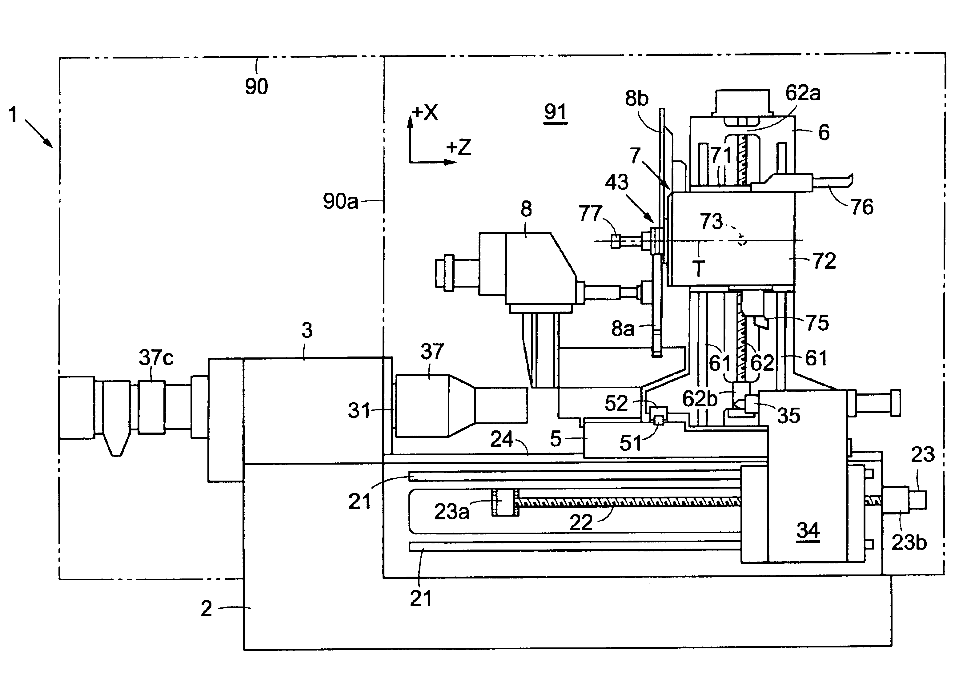
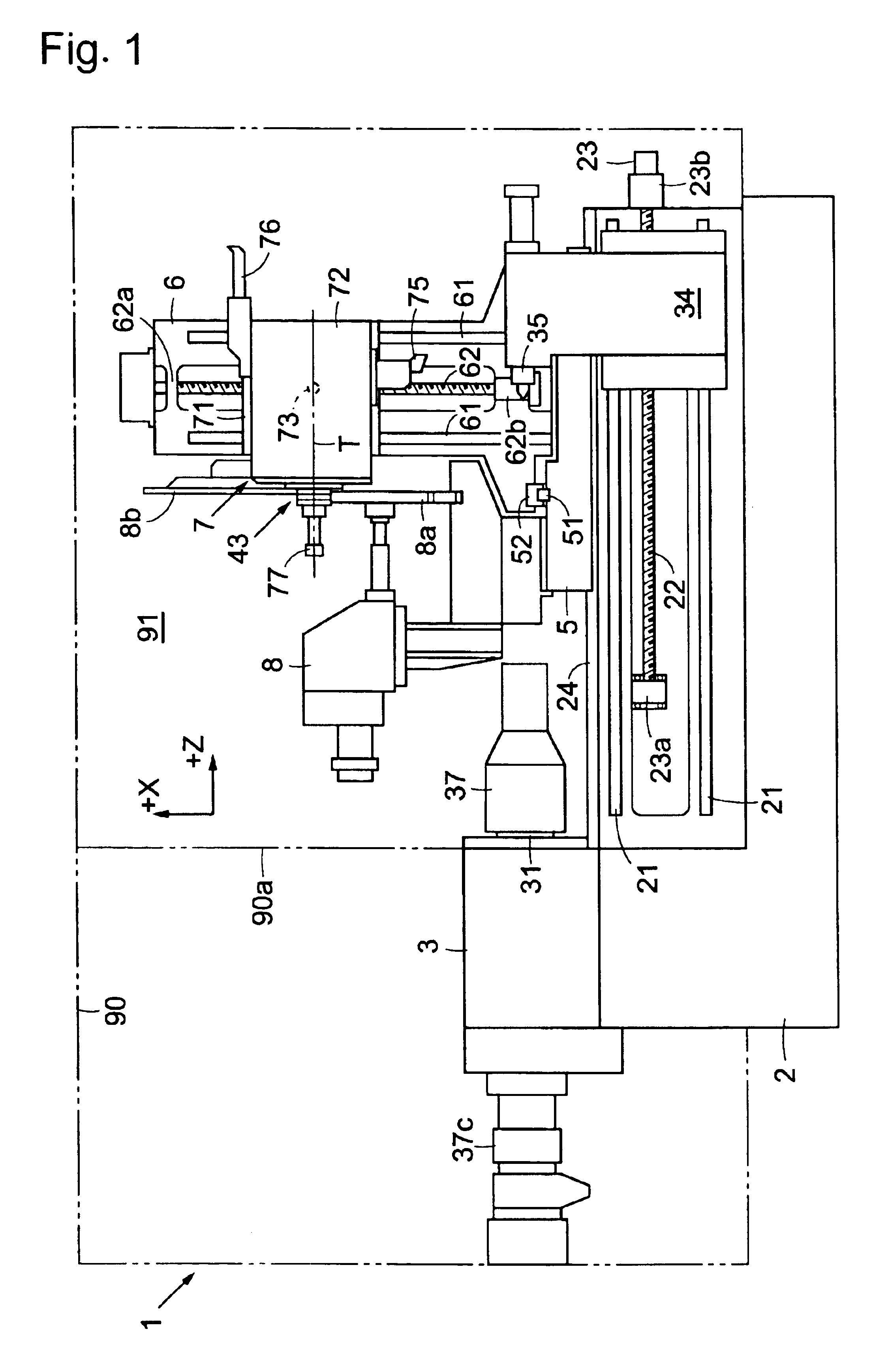
Embodiments of the present invention will be described with reference to the attached figures. FIG. 1 is a diagram which shows the overall construction of the multi-function machine tool 1 of the present invention. A headstock 3 is fastened to a bed 2 which acts as the base of the multi-function machine tool 1. A main spindle 31 which is used for rotational driving of the workpiece is disposed on the headstock 3. The main spindle 31 is disposed so that the center axial line of this main spindle 31 is oriented in the horizontal direction, and the direction of this center axial line is taken as the direction of the Z axis of an orthogonal coordinate system.

Furthermore, workpiece attachment means 37 which are used to attach the workpiece are fastened to the tip end of the main spindle 31. In a state in which the workpiece is attached to the workpiece attachment means 37, the main spindle 31 is rotationally driven by a built-in main spindle motor (not shown in the figures). Furthermore,...


PUM

PropertyMeasurementUnit
distanceaaaaaaaaaa
dimensionaaaaaaaaaa
radiusaaaaaaaaaa

Abstract

The multi-function machine tool of the present invention has a tool rest main body which is disposed movably relative to the main spindle of the machine tool in a first linear direction parallel to the axial line of the main spindle and a second linear direction perpendicular to the axial line of the main spindle, a turning tool rest 72 which is disposed so that this turning tool rest can turn relative to the tool rest main body about a turning axis 73 oriented in a direction that is perpendicular to the first and second linear directions, and control means which control the rotational motion of the main spindle, the turning motion of the turning tool rest about the turning axis, and the relative motion of the tool rest main body. Furthermore, the control means can cause the turning tool rest to perform a turning motion about an arbitrary position that differs from the position of the turning axis by concurrently and synchronously causing a turning motion of the turning tool rest about the turning axis, and a circular-arc motion based on the relative motion of the tool rest main body in the first linear direction and second linear direction.

Description

BACKGROUND OF THE INVENTION1. Field of the InventionThe present invention relates to a multi-function machine tool in which a workpiece held by workpiece attachment means on the tip end of a rotatable main spindle is machined by a tool mounted on a turning tool rest that is capable of a turning motion and a linear motion in two or more directions, and a machining method of this multi-function machine tool; more particularly, the present invention relates to a multi-function machine tool which can machine helical grooves of diverse shapes in the workpiece, and a machining method of this multi-function machine tool.2. Description of the Related ArtThe techniques described in Japanese Patent Publication No. H6-506640 (International Publication No. WO92 / 18278) and Japanese Patent Application Laid-Open No. 3170790 and the like (described later) are known as methods for machining helical grooves of complex shapes in workpieces. A method for forming helical grooves in a screw compressor by...

Claims


Application Information

Patent Timeline
Patent Type & Authority Patents(United States)
IPC IPC(8): B23F15/08B23Q1/25B23F15/00B23F13/00B23Q1/62B23Q11/08B23F13/06B23B21/00B23B3/00B23B3/16B23B5/00B23B5/46B23B5/48B23P23/00B23P23/02G06F19/00B23C3/32
CPCB23B5/48B23F15/08B23Q1/623Y10T82/2543Y10T483/1771B23P23/02
Inventor UEHARA, MASAYAYUHARA, MIWAKO
Owner MORI SEIKI HITECH
Why Eureka
Try Eureka