Tool box

a tool box and tool technology, applied in the field of tool boxes, can solve the problems of difficult removal and replacement, difficult use of tools and the tool box, and prior art does not show a tool box that holds the tool trays in place with magnets

Inactive Publication Date: 2005-03-22
RICHELIEU HARDWARE +1
View PDF22 Cites 56 Cited by
  • Summary
  • Abstract
  • Description
  • Claims
  • Application Information

AI Technical Summary

Problems solved by technology

This intermingling of the tool parts often makes the tools and the tool box difficult to use.
As well, since the tool parts are arranged as close together as possible they are often difficult to remove and replace.
Howeve...

Method used


Image

  • Tool box
  • Tool box
  • Tool box

Examples


Embodiment Construction

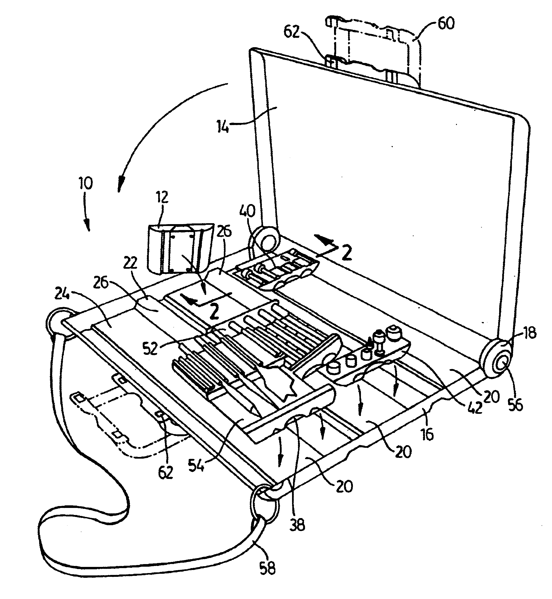
[0019]Referring to FIG. 1, the tool box of the present invention is shown generally at 10. The tool box 10 holds a plurality of easily removable trays 12.

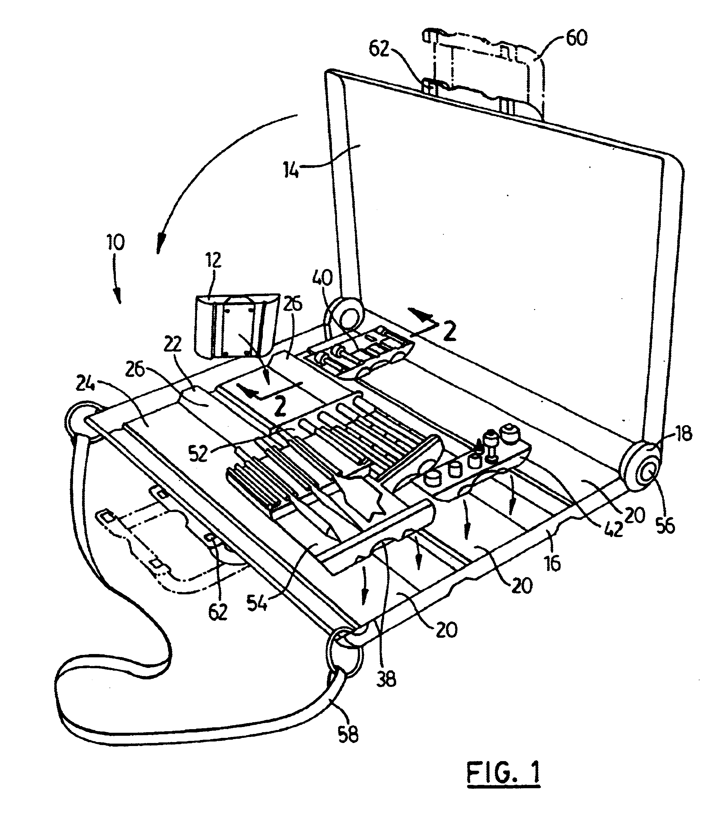
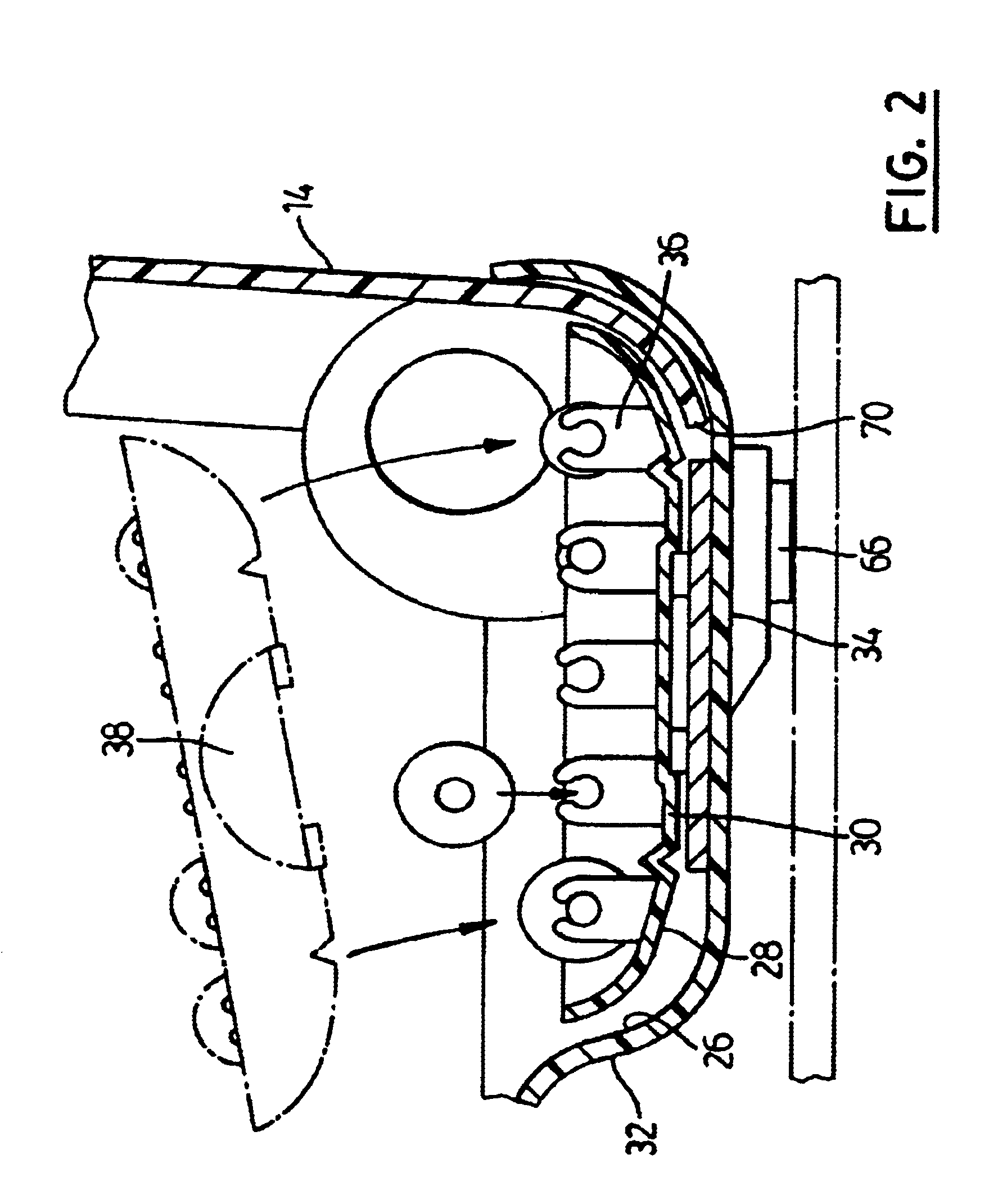
[0020]The tool box has a lid 14 and a base 16 joined by a hinge 18. The base 16 is divided into a plurality of rows 20. Each pair of rows 20 has an elongate ridge 22 therebetween. Each row 20 has a metal portion 24 to which a magnet will attach. Preferably the metal portion 24 is an elongate metal strip which is attached along the bottom of the row 20 and extends along the length thereof. The sides 26 of each row is generally curved inwardly. All of the rows 20 have the same transverse cross section. Preferably lid 14 is transparent. It will be appreciated by those skilled in the art that a wide variety of dimensions may be used for the tool box 10. For example box 10 may be 15 inches long by 12 inches wide by 3 inches deep.

[0021]Referring to FIG. 2, each tray 12 is adapted to receive a predetermined tool, set of tools or parts the...


PUM


Abstract

A tool box is for holding a plurality of tools and tool parts. The tool box includes a base, a lid and at least one tray. The base has at least one row. The lid is attached to the base. Each tray has at least one receiving device adapted to receive one of a predetermined tool and tool part. Each tray is releaseably attachable in a row and includes a magnetic method of holding the tray in the row. The tool box may include a plurality of rows. The magnetic holding method may include a metal strip attached to the bottom of each row and a plurality of magnets attached to the bottom of each tray.

Description

FIELD OF THE INVENTION[0002]This invention relates to tool boxes and in particular tool boxes adapted to store a plurality of different tools and parts thereof.BACKGROUND OF THE INVENTION[0003]Tool boxes are likely almost as old as tools themselves. Tool boxes come in a wide variety of shapes and sizes. Some tool boxes are single function tool boxes that are designed to hold a particular tool, for example a drill or a hand saw. Others are designed to hold a plurality of one type of tool part. Still others are designed to hold a plurality of different tools and / or tool parts.[0004]Typically the tool boxes designed to hold a plurality of different tools and tool parts try to maximize the number of tools in a predetermined space. Accordingly, the tools and tool parts are positioned with an eye to space utilization rather than tool functionality. Accordingly the drill bits may be mixed with screwdriver bits and / or sockets. This intermingling of the tool parts often makes the tools and t...

Claims


Application Information

Patent Timeline
IPC IPC(8): A45C5/00A45C13/02B25H3/02B25H3/06
CPCA45C5/00A45C13/02B25H3/021B25H3/06Y10S206/818
Inventor LAM, ANDY
Owner RICHELIEU HARDWARE
Why Eureka
Try Eureka