
Projector with improved focus ring

Inactive Publication Date: 2005-03-22
FUNAI ELECTRIC CO LTD
View PDF8 Cites 5 Cited by
  • Summary
  • Abstract
  • Description
  • Claims
  • Application Information

AI Technical Summary

Benefits of technology

The present invention is made to solve the above-described problems, and an object thereof is to provide a projector having a focus ring capable of being easily attached to a lens main body and being easily molded.
With this structure, the focus ring is inserted into the lens main body at an optional position without specifying the position of the pair of protrusion parts formed on the focus ring in the circumferential direction and the focus ring is turned, whereby the first rib is sandwiched between the pair of protrusion parts. Therefore, the movement of the focus ring in the circumferential direction is restricted with respect to the lens body. In addition, in this state, the second rib is brought into contact with and engaged with the backward portion of the pair of protrusion parts in the insertion direction, whereby the movement of the focus ring in the optical axis direction is restricted with respect to the lens main body. As a result, it is possible to easily fix the focus ring to the lens main body. In addition, the structure has no necessity to provide an opening for receiving a protrusion in a circumferential direction like a focus ring of the conventional projector, and makes it possible to further simplify the structure of a die for molding a focus ring.
With this structure, the focus ring is inserted into the lens main body at an optional position without specifying the position of the pair of protrusion parts formed on the focus ring in the circumferential direction and the focus ring is turned, whereby the one portion is sandwiched between the another portions in the circumferential direction. Therefore, the movement of the focus ring in the circumferential direction is restricted with respect to the lens body. In addition, in this state, the one portion is engaged with the another portions along the optical axis, whereby the movement of the focus ring in the optical axis direction is restricted with respect to the lens main body. As a result, it is possible to easily fix the focus ring to the lens main body.
With this structure, the focus ring can be comparatively easily detached from the lens main body by pulling out focus ring fixed to lens main body in a direction opposite to the attachment direction.
With this structure, a portion, on which a protrusion is formed at the time of attaching the focus ring to the lens main body, is flexed, so that the focus ring can be easily fixed to the lens main body. In addition, the structure has no necessity to provide an opening for receiving a protrusion in a circumferential direction like a focus ring of the conventional projector, and makes it possible to simplify the structure of a die for molding a focus ring.
With this structure, it is possible to suppress the focus ring from easily deforming due to the heat generated at the time of projecting a picture.

Problems solved by technology

However, the conventional projector has the following problems.
Therefore, a problem has arisen in that the structure of the die is complicated.

Method used


Image

  • Projector with improved focus ring
  • Projector with improved focus ring
  • Projector with improved focus ring

Examples


Embodiment Construction

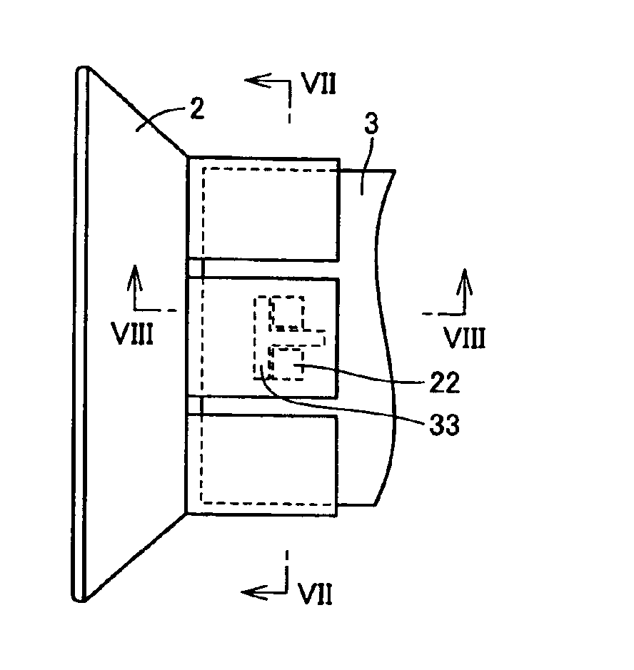
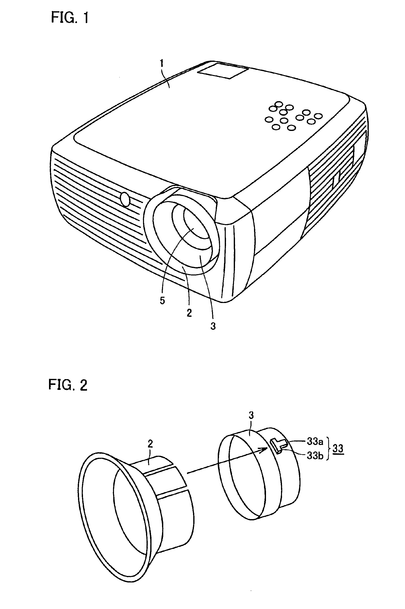
Description will be given of a projector according to an embodiment of the present invention. As shown in FIG. 1, a focus ring 2 is attached to a lens main body 5 of a projector 1 through a projection ring 3.

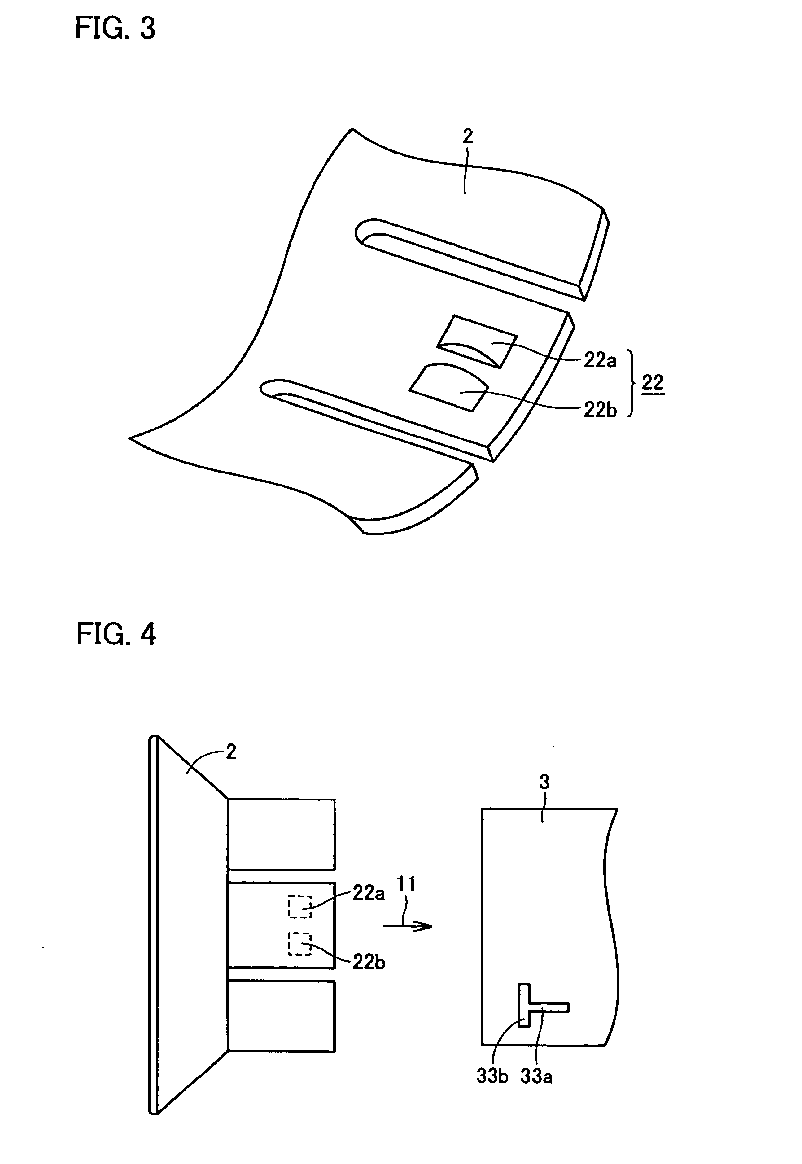
As shown in FIG. 2, a prescribed rib 33 is provided on an outer periphery of projection ring 3. Rib 33 includes: a first rib 33a extending along a direction in which an optical axis of lens main body 5 extends (an attachment direction of focus ring 2); and a second rib 33b, brought into contact with one end of first rib 33a, extending along a direction approximately orthogonal to first rib 33a so as to have one side and the other side.

On the other hand, as shown in FIG. 3, a prescribed protrusion 22 is provided on an inner periphery of cylindrical focus ring 2. Protrusion 22 includes a pair of protrusion parts 22a, 22b arranged with a spacing in a direction approximately orthogonal to the direction in which the optical axis extends. The pair of protrusion parts 22a, 22b is forme...


PUM


Abstract

A rib, provided on an outer periphery of a projection ring, includes: a first rib extending along a direction in which an optical axis of a lens main body extends (an attachment direction of a focus lens); and a second rib, brought into contact with one end of first rib, extending along a direction approximately orthogonal to first rib so as to have one side and the other side. On the other hand, a protrusion, provided on an inner periphery of the cylindrical focus ring, includes a pair of protrusion parts arranged with a spacing in a direction in which an optical axis extends. With this structure, it is possible to obtain a projector having a focus ring capable of being easily attached to a lens main body and being easily molded.

Description

BACKGROUND OF THE INVENTION1. Field of the InventionThe present invention relates to a projector and, particularly, to a projector having a focus ring.2. Description of the Background ArtThere has been a projector as one of devices for projecting a picture on a screen. A lens main body for projecting a picture is attached to the projector. As shown in FIG. 10, a focus ring 102 is generally attached to a lens main body 105. Lens main body 105 with focus ring 102 has a diameter larger than that of lens main body 105 without focus ring 102, thereby easily achieving focusing.In lens main body 105, a lens itself is attached to a projection ring 103. Projection ring 103 is provided with a protrusion 103a protruded outwardly.On the other hand, focus ring 102 is provided with a slit 104 for receiving protrusion 103a. Slit 104 includes: an opening 102a for receiving protrusion 103a; and a passage 102b which is narrower than opening 102a. Focus ring 102 is generally made of resin.Next, descri...

Claims


Application Information

Patent Timeline
IPC IPC(8): G03B3/00G03B3/02G03B23/00
CPCG03B23/00G03B3/02
Inventor HAMADA, SHINGO
Owner FUNAI ELECTRIC CO LTD
Learn More