Double layer spacer for antiparallel pinned layer in CIP/CPP GMR and MTJ devices

a technology of antiparallel pinned layer and double layer spacer, which is applied in the field of gmr devices, can solve the problems that hs cannot be too great, the annealing process is not required to set the field direction of the pinned layer, and the technology of pinned layer field direction is too high, so as to achieve good stability and dr/r, the resistance of bilayered combination is greater, and the resistivity is lower

Inactive Publication Date: 2005-03-22
HEADWAY TECH INC
View PDF8 Cites 17 Cited by
  • Summary
  • Abstract
  • Description
  • Claims
  • Application Information

AI Technical Summary

Benefits of technology

A third object of this invention is to provide such a pinned layer which offers both a high value of Hs and a high value of dR / R, both of which contribute to the desired stability of the layer and the performance of the sensor.
These objects will be met by coupling AP1 and AP2 across a novel coupling layer that is a bilayer of Ru / Rh or Rh / Ru, wherein Ru and Rh separately provide coupling strengths which are relatively weak and relatively too strong respectively. Furthermore, the resistance of the bilayered combination is greater than that of a layer of Rh alone because the resistivity of Rh is lower than that of Ru. The bilayer gives us two adjustable parameters, the thickness of the Ru portion and the thickness of the Rh portion, which can be adjusted to provide both good stability and dR / R.

Problems solved by technology

The GMR (giant magneto-resistive) sensor and its operation are easy to describe conceptually, although the technological developments that have led to its present form are quite complex.
Although a high Hs is desirable, there is a conflict between too high a value and the limitations of the annealing process required to set the pinned layer field direction.
Since the maximum available magnetic field in commercially available heating ovens is typically between 10 and 20 kOe, this means that Hs cannot be too great.
Thus, by using Rh instead of Ru a much stronger coupling between AP1 and AP2 is obtained, but, conversely, magnetic annealing becomes nearly impossible.

Method used


Image

  • Double layer spacer for antiparallel pinned layer in CIP/CPP GMR and MTJ devices
  • Double layer spacer for antiparallel pinned layer in CIP/CPP GMR and MTJ devices

Examples


Embodiment Construction

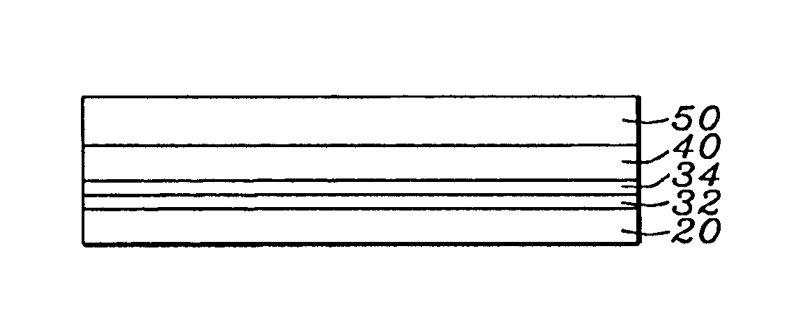
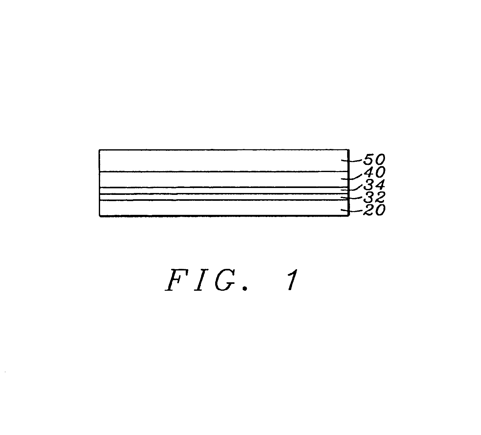
The preferred embodiment of the present invention is a pinned / pinning layer structure of the form:AP1 / coupling layer / AP2 / AFM

wherein the coupling layer is a novel bilayer of Ru / Rh or Rh / Ru. The bilayer combination provides two adjustable parameters, the thicknesses of the Rh and Ru layers, by whose adjustment a wide range of coupling strengths can be obtained. This structure can be incorporated into a wide range of devices that use the GMR effect, including GMR sensors of the CIP and CPP configuration and TMR devices such as MRAM elements. Each of these devices will be improved in their performance characteristics, as measured by such parameters as dR / R, by the inclusion of a pinned / pinning layer structure of improved stability.

Referring now to FIG. 1, there is shown the structure of the present invention as it would appear when incorporated into a sensor or an MRAM cell. Layer AP1 (20) is a layer of ferromagnetic material such as CoFe, layer AP2 (40) is a second layer of ferromagnet...


PUM

PropertyMeasurementUnit
thicknessaaaaaaaaaa
thicknessaaaaaaaaaa
thicknessaaaaaaaaaa

Abstract

A pinned / pinning layer configuration of the form: AP1 / coupling bilayer / AP2 / AFM, suitable for use in a CIP or CPP GMR sensor, a TMR sensor or an MRAM element, is found to have improved magnetic stability, yield good values of dR / R and have high values of saturation magnetization that can be adjusted to meet the requirements of magnetic field annealing. The coupling bilayer is a layer of Ru / Rh or their alloys, which provides a wide range of coupling strengths by varying either the thickness of the Ru layer or the Rh layer.

Description

BACKGROUND OF THE INVENTION1. Field of the InventionThis invention relates generally to all GMR devices having synthetic, antiparallel coupled pinned layers and, more particularly, to a novel coupling layer that provides greater stability for the coupling.2. Description of the Related ArtThe GMR (giant magneto-resistive) sensor and its operation are easy to describe conceptually, although the technological developments that have led to its present form are quite complex. Basically the GMR sensor consists of two magnetic layers, formed vertically above each other in a parallel planar configuration and separated by a non-magnetic layer. Each magnetic layer has a magnetic moment in the plane of the layer. When a “sense” current passes between the planes it is subject to resistance variations, dR, which are proportional to the angle between the magnetization directions. These variations are measured by voltage variations between the ends of the sensor. The quality of the sensor is measu...

Claims


Application Information

Patent Timeline
Patent Type & Authority Patents(United States)
IPC IPC(8): G11B5/39
CPCG11B5/39Y10T29/49044
Inventor ZHAO, TONGWANG, HUI-CHUANLI, YUN-FEITORNG, CHYU-JIUH
Owner HEADWAY TECH INC
Why Eureka
Try Eureka