Video recorder for recording moving and still picture information

a video recorder and moving picture technology, applied in the field of video signal recording apparatus, can solve problems such as inability to realize the desire to record some moving picture information such as shown in fig. 5

Inactive Publication Date: 2005-03-22
JVC KENWOOD CORP A CORP OF JAPAN
View PDF4 Cites 104 Cited by
  • Summary
  • Abstract
  • Description
  • Claims
  • Application Information

AI Technical Summary

Benefits of technology

Accordingly, in consideration of the above-mentioned problem of the prior art, an object of the present invention is to provide a recording apparatus of a video signal and a recording method of the video signal, which can simultaneously confirm a moving picture information and a still picture information by displaying both the still picture information and the moving picture information simultaneousl

Problems solved by technology

Accordingly, there existed a problem that a desire for recording some moving picture information su

Method used


Image

  • Video recorder for recording moving and still picture information
  • Video recorder for recording moving and still picture information
  • Video recorder for recording moving and still picture information

Examples


first embodiment

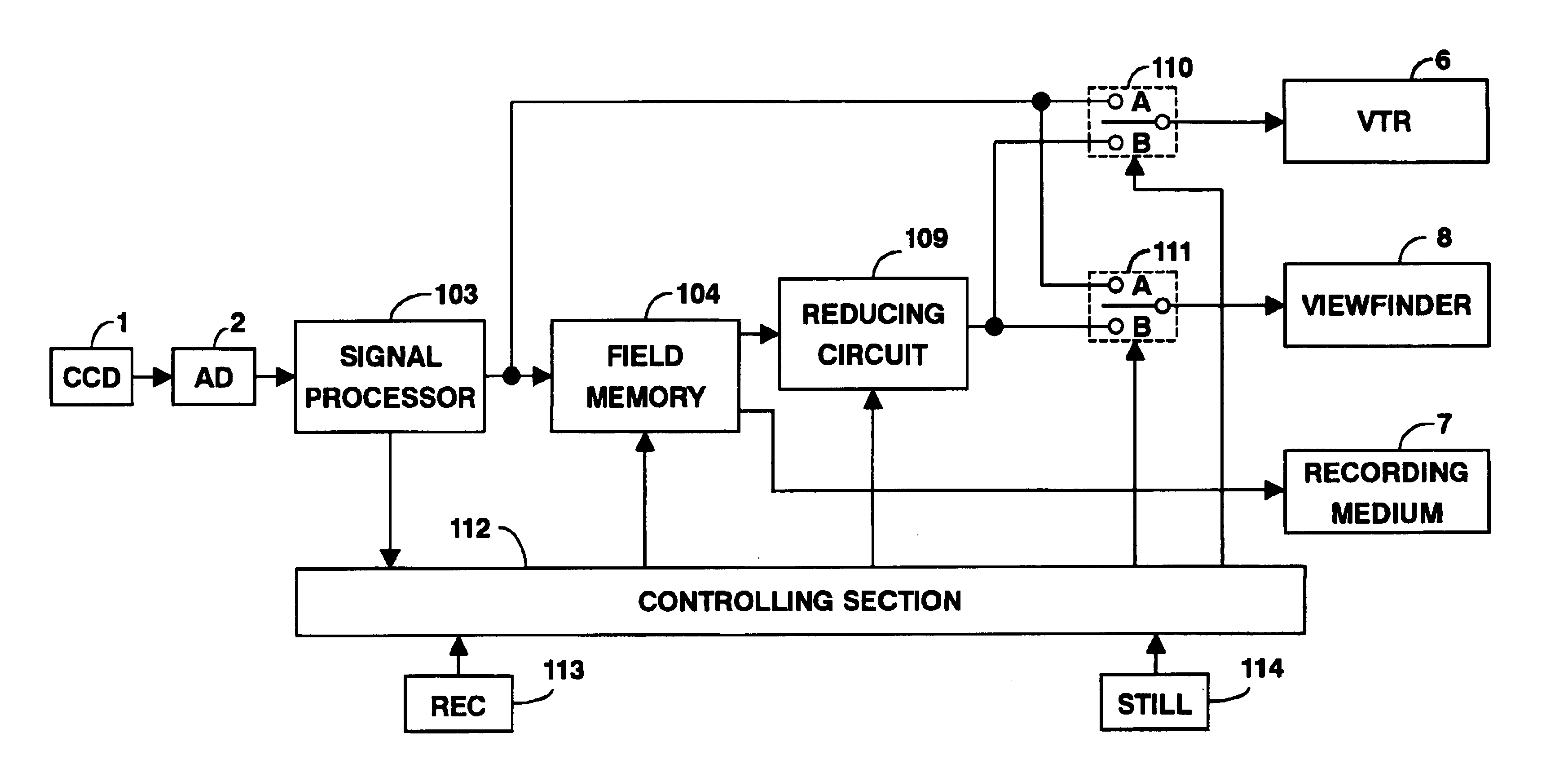
FIG. 1 is a block diagram of a recording apparatus of a video signal according to a first embodiment of the present invention.

FIG. 4 shows an exemplary indication of a still picture information.

FIG. 5 shows an exemplary indication of a moving picture information.

FIG. 6 shows an exemplary indication of superimposing a still picture information on a moving picture information.

In FIG. 1, a recording apparatus of a video signal comprises a CCD (charge coupled device) 1, an analog to digital converter (AD) 2, a signal processor 103, a field memory 104, a reducing circuit 109, a first switch 110, a second switch 111, a controlling section 112, a recording (REC) switch 113, a still (STILL) switch 114, a video tape recorder (VTR) 6, a recording medium 7 and a view finder 8. The CCD 1 is an image sensing device. The AD 2 converts an analog signal outputted from the CCD 1 into a digital signal. The signal processor 103 converts a digital video signal outputted from the AD 2 into a luminance s...

second embodiment

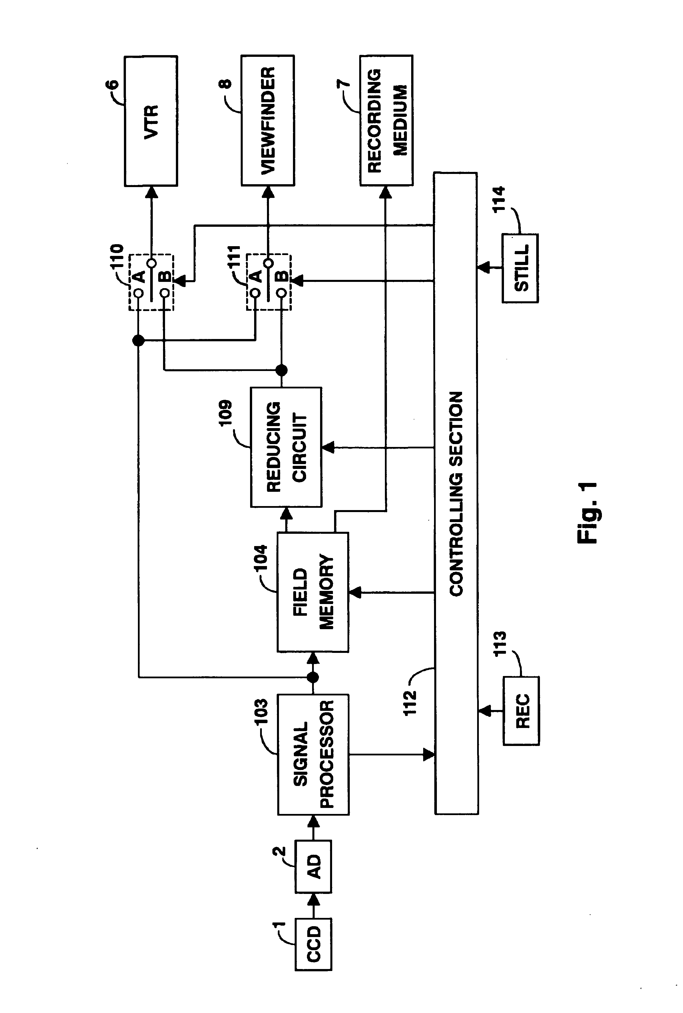
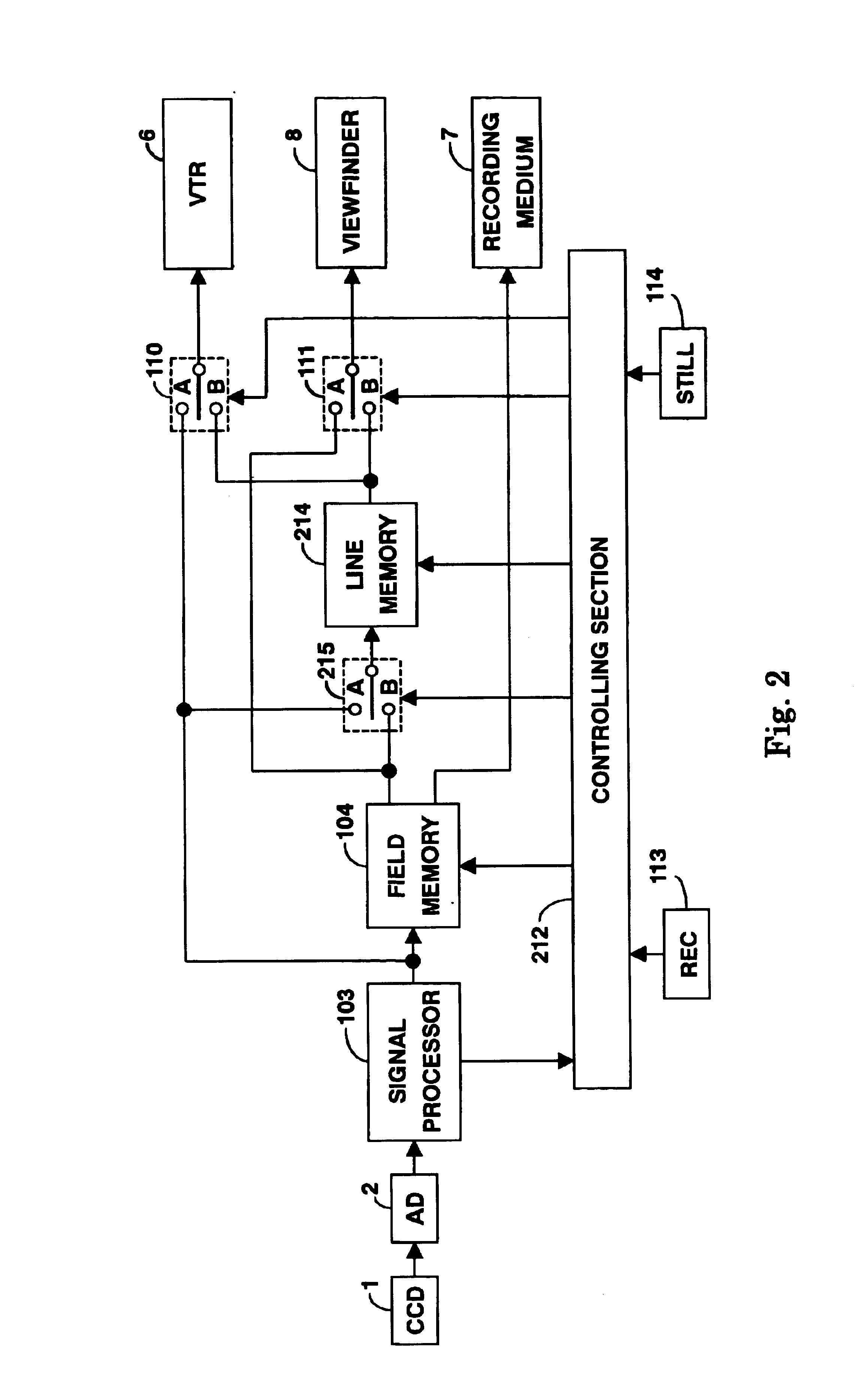
FIG. 2 is a block diagram of a recording apparatus of a video signal according to a second embodiment of the present invention.

In FIG. 2, a recording apparatus comprises the CCD 1, the AD 2, the signal processor 103, the field memory 104, a third switch 215, a line memory 214, the first switch 110, the second switch 111, a controlling section 212, the REC switch 113, the STILL switch 114, the VTR 6, the recording medium 7 and the viewfinder 8. The recording apparatus depicted in the second embodiment is similar to that of the first embodiment shown in FIG. 1 and further comprises the third switch 215 and the line memory 216 in addition to the recording apparatus of the first embodiment shown in FIG. 1. The third switch 215 selectively switches a digital video signal (moving picture information) outputted from the signal processor 103 over to a digital video signal (still picture information) from the field memory 104 or vice versa and outputs a selected digital signal to the VTR 6. ...

third embodiment

FIG. 3 is a block diagram of a recording apparatus of a video signal according to a third embodiment of the present invention.

FIG. 9 shows an exemplary indication of superimposing a moving picture information on a still picture information.

In FIG. 3, a recording apparatus comprises the CCD 1, the AD 2, the signal processor 103, a first field memory 104, a second field memory 341, a third switch 315, a fourth switch 316, the reducing circuit 109, the first switch 110, the second switch 111, a controlling section 312, the REC switch 113, the STILL switch 114, the VTR 6, the recording medium 7 and the viewfinder 8. The recording apparatus depicted in the third embodiment is similar to that of the first embodiment shown in FIG. 1 and further constituted such that the second field memory 341 is provided between the signal processor 103 and the terminal “A” of the first switch 110, the fourth switch 316 is inserted after the second field memory 341, and the third switch 315 is provided pr...


PUM


Abstract

When a still picture information is recorded on the recording medium 7 while a moving picture information is recorded by the VTR 6, a still picture information to be recorded can be confirmed and recorded by displaying the still picture information to be recorded in a sub picture frame on the screen of the viewfinder 8, which displays the moving picture information currently recorded.

Description

BACKGROUND OF THE INVENTION1. Field of the InventionThe present invention relates to a recording apparatus of a video signal and a recording method of the video signal, particularly, relates to a recording apparatus of a video signal, which can record both moving picture information and still picture information, and a recording method of the video signal for recording both the moving picture information and the still picture information.2. Description of the Related ArtThere provided a video signal recording apparatus, which comprises a video camera equipped with an image sensing device such as a CCD (charge coupled device) and a recording and reproducing apparatus for recording a video signal on a recording medium such as a magnetic tape being organized in one body. Such the video signal recording apparatus is mainly utilized for recording a moving picture information. However, a recording apparatus, which can record both moving picture information and still picture information, h...

Claims


Application Information

Patent Timeline
IPC IPC(8): H04N5/926H04N9/79H04N5/232H04N5/77H04N5/781H04N5/907
CPCH04N5/23293H04N5/772H04N9/7921H04N5/9261H04N5/907H04N5/781H04N23/635
Inventor TAGUCHI, KENJIMATSUKAWA, NOBUYUKIKATOH, HIDEHIROMIYAHARA, HIROYUKIASO, MICHIHIROOHTSUKA, TAKAYUKI
Owner JVC KENWOOD CORP A CORP OF JAPAN
Why Eureka
Try Eureka