Inhaler

Inactive Publication Date: 2005-03-29
ADVENT PHARMA PTY LTD
View PDF21 Cites 138 Cited by
  • Summary
  • Abstract
  • Description
  • Claims
  • Application Information

AI Technical Summary

Problems solved by technology

There is also a problem with inhalers of this kind if there is a tendency to allow unintentional additional dosing.

Method used


Image

  • Inhaler
  • Inhaler
  • Inhaler

Examples


second embodiment

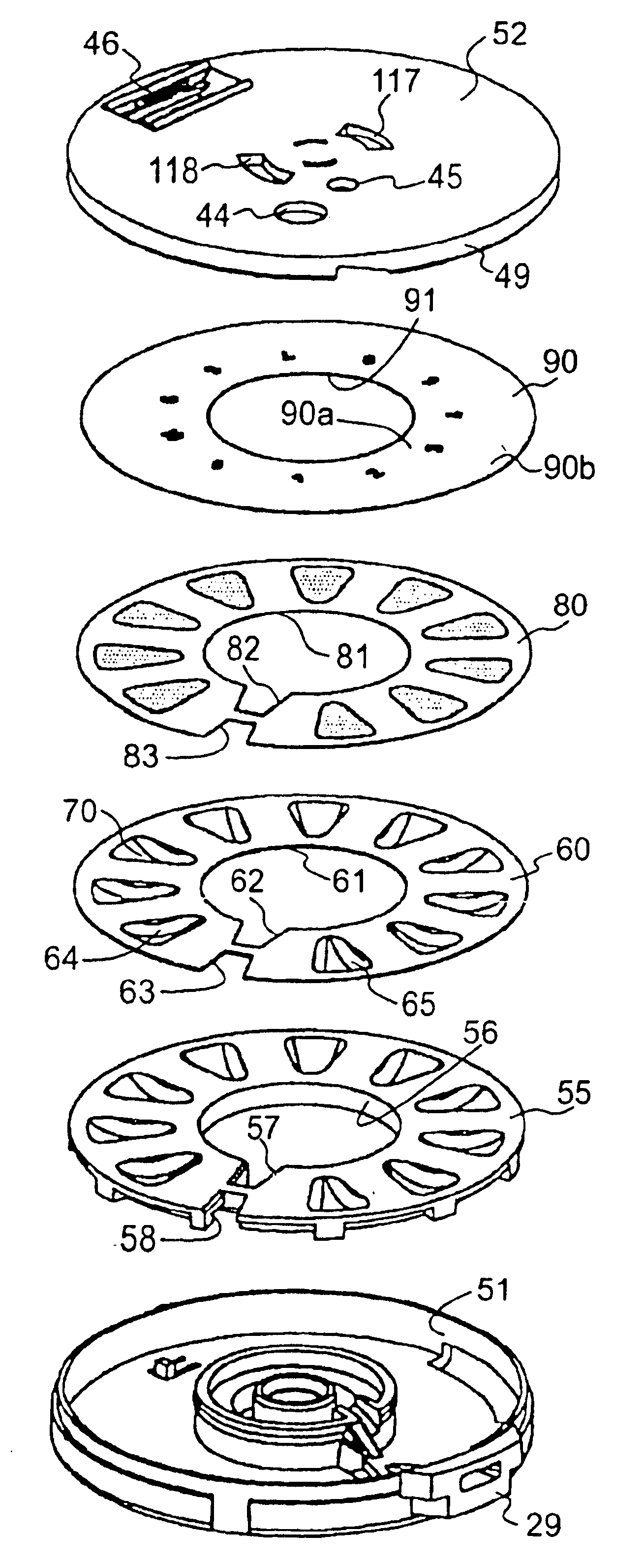
FIGS. 15 to 17 illustrate a second embodiment that utilises a different cartridge which is shown in FIG. 15. The cartridge 150 has a slit top foil layer 190 provided with radial slits 192 that define segments that correspond to the position of each compartment. The top foil layer 190 has a central aperture 191 and is bonded to the lower foil 160 to seal off the compartments 170. A circular assembly 180 of flip top members 181 is bonded to the top foil 190. The assembly 180 comprises a plastics moulding in the form of a plurality of radially extending flip top members 181 that are interconnected by circumferentially extending webs 182. Each flip top member 181 comprises a radially outer arm 184 that is joined to a V-shaped inner arm 185 by the webs 182 that interconnect that flip top member 181 to the adjacent flip top members. The underside of both the radially outer and inner arms include downwardly projecting triangular shaped lugs 187 and 188. The bonding of the assembly 180 to t...

first embodiment

The assembly of the disc base 151, two foil layers 160 and 190 and flip top assembly 180 is then covered by a plastics cover 195 that has a central aperture 196 and a downwardly extending annular skirt 197 that covers the components. An arcuate cutout 198 is provided in the periphery of the skirt 197 of the cover 195 through which a lever (not shown), similar to the first embodiment, can extend to engage the disc base 151. The rotation of the disc base 151 and foil layers 160 and 190 and flip top assembly 180 relative to the cover 195 is illustrated in FIG. 16. An arcuate cutout 199 is provided in the periphery of the skirt 197 of the cover 195 which, prevents the base rotating in the wrong direction by engaging the disc base 151.

Displacement of the lever rotates the disc base 151 causing the inner and outer lugs 187, 188 on the flip top member 181 to ride up on radial projections on the base of the inhaler (not shown) to cause the arms 184, 185 of the flip top members 181 to flex u...

third embodiment

In the third embodiment shown in FIGS. 18 and 19, the disc base 251 and lower foil 260 are provided with radially inner and outer cutouts 252, 253, 262, 263 in the gap 268 between the first and last compartment 264, 265. The cut-outs 252, 253, 262, 263 accommodate a disc opener 220 in the form of a bracket having a flat base 221 terminating an upstanding posts 222, 223, 224, 225 at either end with the posts having inturned downwardly extending flanges 226. The posts and flanges 226 are positioned on the radially outer and radially inner end of the opener 220 and allow the opener to clip against the underside of the disc base 251 with the flat base 221 in parallel sliding contact with the underside of disc base 251 and the flanges 226 extending across the lower foil 260 surface but beneath the upper foil 290. The disc opener 220 is located in the cover 250 of the cartridge in a manner that it cannot rotate with the disc base 251 so that as the disc base is rotated the leading edges o...


PUM


Abstract

An inhaler for delivering metered doses of powdered medicament, the inhaler having a plurality of compartments spaced in an array and each arranged to contain a metered dose of the medicament, a lever to displace the compartments one by one into line with an inhalation aperture that constitutes a mouthpiece, each compartment including inner and outer edges, the plurality of compartments being closed by a sealing layer, the inhaler further having a mechanism adapted to lift the sealing layer off the inner and outer edges of the compartment to open an air passageway defined by the compartment and the sealing layer so that, in use, on inhalation through the mouthpiece, air flow in the air flow passageway picks up and entrains the powder in the compartment to be drawn with the air out of the inhaler through the mouthpiece.

Description

BACKGROUND OF THE INVENTIONThere are many types of inhalers that can provide delivered metered doses. The majority of inhalers of this kind are designed to provide multiple doses. It is however known that inhalers of this kind can also be used to provide a single dose.In situations where a metered dose is to be dispensed it is important that the inhaler always dispenses the exact dose. There is also a problem with inhalers of this kind if there is a tendency to allow unintentional additional dosing. Inhalers need to be small, compact, easy to use and yet not too expensive. The inhalers also need to satisfy safety criteria set down by appropriate standards.It is these issues that have brought about the present invention.SUMMARY OF THE INVENTIONIn accordance with one aspect of the present invention there is provided an inhaler for delivering metered doses of powdered medicament, the inhaler having a plurality of compartments spaced in an array and each arranged to contain a metered do...

Claims


Application Information

Patent Timeline
Patent Type & Authority Patents(United States)
IPC IPC(8): A61M15/00
CPCA61M15/0045A61M11/003A61M15/0071A61M15/0025A61M15/0031A61M15/0043A61M15/0048A61M15/0015A61M2202/064A61M2205/583
Inventor ALLAN, ROBERT DAVIDPIKE, GREGORY CHARLES
Owner ADVENT PHARMA PTY LTD
Why Eureka
Try Eureka