Driveshaft with counter-track joint

a technology of drive shaft and counter-track joint, which is applied in the direction of yielding coupling, control device, rotary machine parts, etc., can solve problems such as joint control, and achieve the effect of improving cage control conditions and improving control characteristics

Inactive Publication Date: 2005-03-29
GKN AUTOMOTIVE GMBH
View PDF10 Cites 10 Cited by
  • Summary
  • Abstract
  • Description
  • Claims
  • Application Information

AI Technical Summary

Benefits of technology

The present invention provides a driveshaft of the initially mentioned type with a counter-track joint with improved control characteristics. The counter-track joint includes first pairs of tracks positioned radially opposite other first pairs of tracks, and second pairs of tracks positioned radially opposite other second pairs of tracks. More particularly, the first pairs of tracks and second pairs of tracks are arranged so as to alternate across the circumference. In another embodiment, a joint with eight uniformly circumferentially distributed pairs of tracks is disclosed. Other joint embodiments include twelve or sixteen pairs of tracks. An inventive driveshaft with such a joint is characterised by a clearly improved service life of the joint which, in particular, is used as a joint at the drive end in a driveshaft consisting of two fixed constant velocity joints and an intermediate shaft with an integrated axial plunging unit. The outer joint part is driven by the differential drive and the inner joint part is connected to the intermediate shaft. The improved service life is due to the resulting control forces which permanently deviate from zero and which are applied by pairs of tracks to the respective opposed pairs of balls, so that, overall, the cage control conditions are much improved. The reasons for such improved control force conditions will be explained with reference to the drawings.

Problems solved by technology

This design has disadvantages with regard to joint control, i.e. the control force conditions at the cage.

Method used


Image

  • Driveshaft with counter-track joint
  • Driveshaft with counter-track joint
  • Driveshaft with counter-track joint

Examples


Embodiment Construction

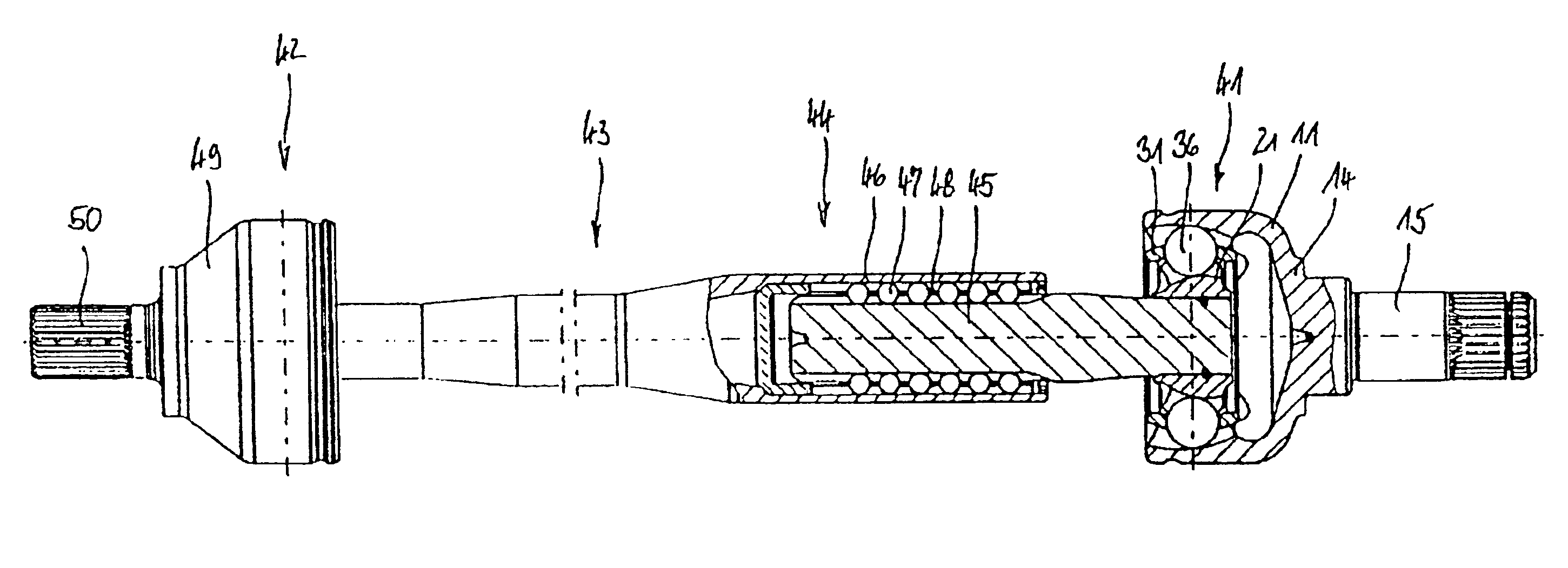
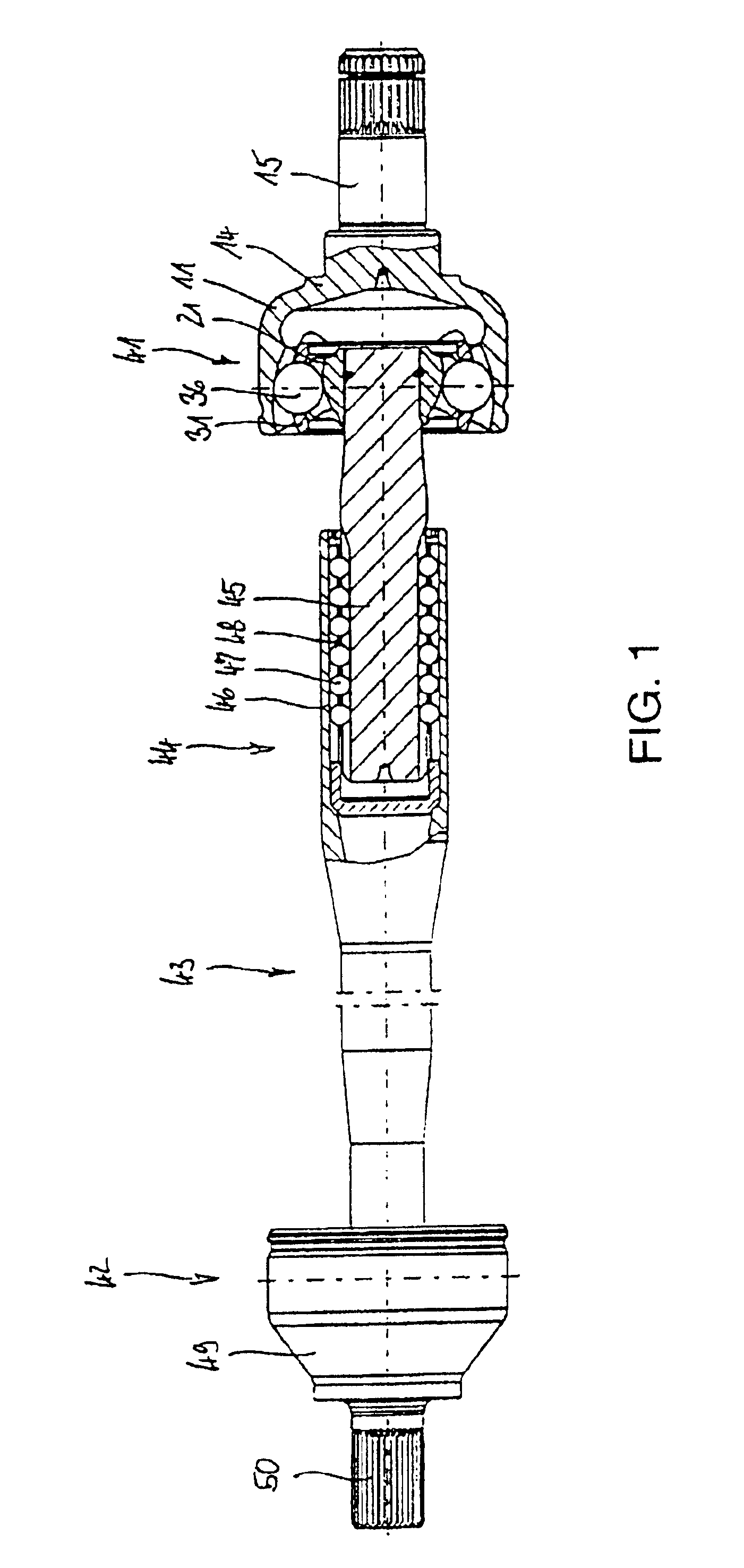
FIG. 1 shows an inventive driveshaft with a first constant velocity fixed ball joint 41 in the form of a counter-track joint, a second constant velocity fixed ball joint 42 and an intermediate shaft 43. The intermediate shaft 43 includes an integrated axial plunging unit 44 which, substantially, comprises a journal 45, a sleeve 46 and torque transmitting balls 47 which are held together by a cage 48. The first constant velocity fixed ball joint 41 comprises an outer joint part 11 with a base 14 and a formed-on journal 15, as well as an inner joint part 21 connected to the journal 45, a ball cage 31 and torque transmitting balls 36. The joint and thus the entire driveshaft are driven by the journal 15 via the outer joint part 11. The journal 15 is inserted into a differential drive, for example. The second constant velocity fixed ball joint 42 is arranged in such a way that output is effected via a journal 50 which is connected to its outer joint part 49 and to a wheel hub, for examp...


PUM


Abstract

A driveshaft having at least one counter-track joint, the joint having an outer joint part (11), an inner joint part (21), torque-transmitting balls (36) accommodated in pairs of tracks, and a ball cage with cage windows in which the balls are held in a common plane. First outer tracks and first inner tracks form first pairs of tracks which diverge from one another when viewed in a first axial direction towards the connection end of the inner joint part (21) and hold first balls. Second outer tracks and second inner tracks form second pairs of tracks which diverge from one another when viewed in a second axial direction towards the connection end of the outer joint part 11 and hold second balls. The first pairs of tracks are positioned radially opposite each other and the second pairs of tracks are positioned radially opposite each other.

Description

TECHNICAL FIELDThe invention relates to a driveshaft having two constant velocity joints and an intermediate shaft, such as a sideshaft in a motor vehicle, wherein the driveshaft has at least one constant velocity fixed ball joint in the form of a counter-track joint. The counter-track joint comprises an outer joint part with outer tracks, an inner joint part with inner tracks, torque-transmitting balls accommodated in pairs of tracks consisting of outer tracks and inner tracks, and a ball cage with cage windows in which the balls are held in a common plane and are guided on to the angle-bisecting plane when the joint is articulated. First outer tracks, together with first inner tracks, form first pairs of tracks which diverge from one another when viewed in a first axial direction towards the connection end of the inner joint part and hold first balls. Second outer tracks, together with second inner tracks, form second pairs of tracks which diverge from one another when viewed in a...

Claims


Application Information

Patent Timeline
Patent Type & Authority Patents(United States)
IPC IPC(8): B60K17/22F16D3/16F16D3/227F16D3/224F16D3/223
CPCF16D3/065F16D3/223B60K17/22Y10S464/906F16D2003/22306
Inventor WECKERLING, THOMASMAUCHER, STEPHANGREMMELMAIER, ANNATAUREG, HERBERT
Owner GKN AUTOMOTIVE GMBH
Why Eureka
Try Eureka