Pneumatically actuated swing ride

a pneumatic actuator and swing technology, applied in swings, amusements, entertainment, etc., can solve the problems of not giving the prolonged feeling of weightlessness, difficult to maintain, and weightlessness in the ride, and achieve the effect of prolonging the feeling of weightlessness and easy adjustmen

Inactive Publication Date: 2005-04-05
S&S WORLDWIDE
View PDF5 Cites 24 Cited by
  • Summary
  • Abstract
  • Description
  • Claims
  • Application Information

AI Technical Summary

Benefits of technology

Another object of this invention is to create a pneumatically actuated swing ride that can be easily adjusted from a high-speed ride to a modest-speed ride during the ride or between rides.
Another object of this invention is to create a pneumatically actuated swing ride that can give the same prolonged feeling of weightlessness during each cycle of the ride.

Problems solved by technology

The controlled upward movement, a brief delay, and the accelerated downward movement produce weightlessness in the ride that is unmatched in the industry.
It has a high degree of sophisticated machinery and apparatus on the elevated levels of the device, which make it extremely difficult to maintain.
The ride produces only a variety of swinging movements and does not give the prolonged feeling of weightlessness.
Again, this device does not give a complete feeling of weightlessness.
The duration of the ride cannot be controlled and there again this device does not give a repeated feeling of weightlessness derived by the pneumatically actuated swing ride.
These rides handle a large number of people for a controlled time and are not commonly found permanently anchored to the ground.
This is still another swing ride where the riders go through a progressively decreasing pendulum motion until the ride is over, and does not give a complete feeling of weightlessness.

Method used


Image

  • Pneumatically actuated swing ride
  • Pneumatically actuated swing ride
  • Pneumatically actuated swing ride

Examples


Embodiment Construction

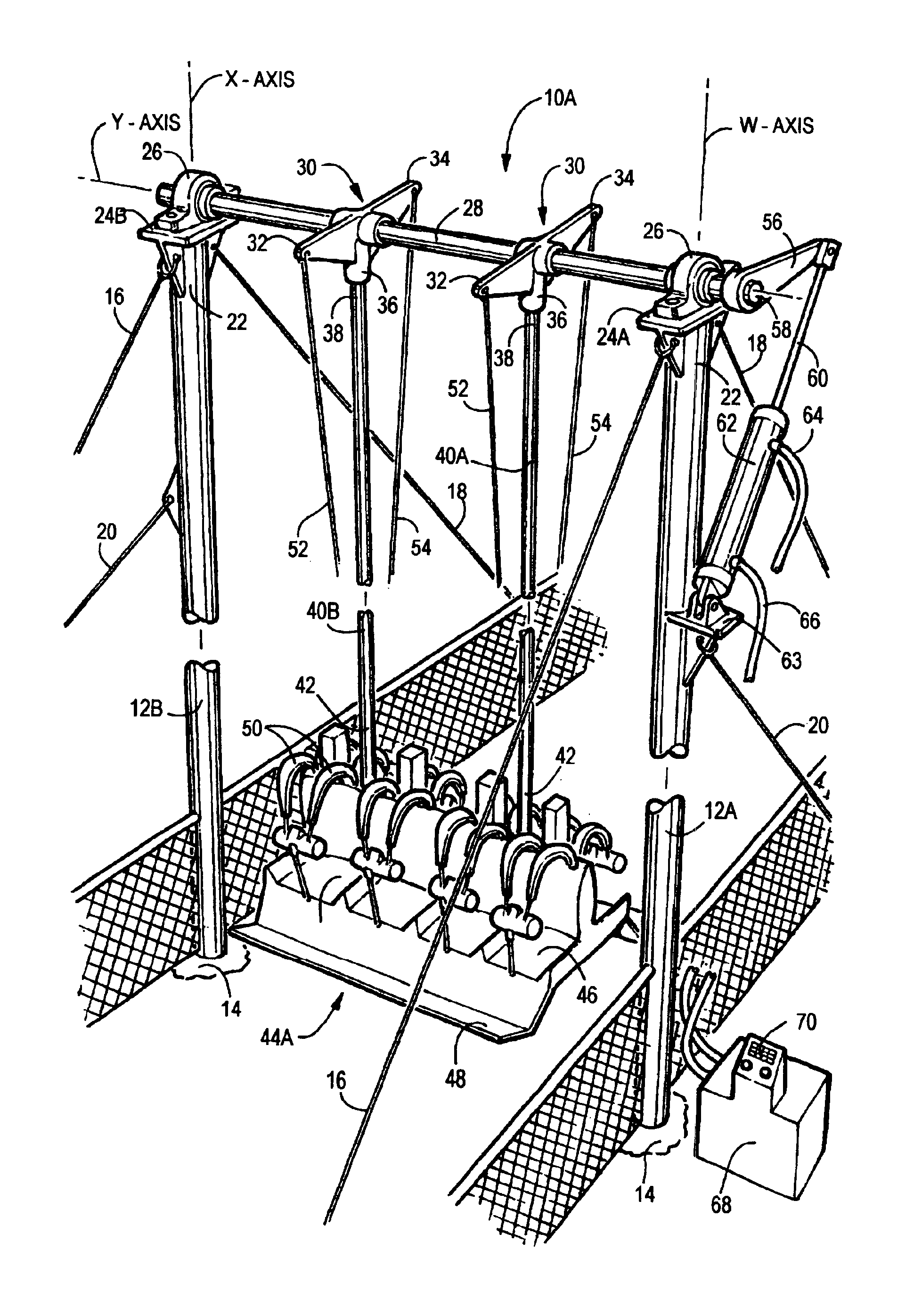
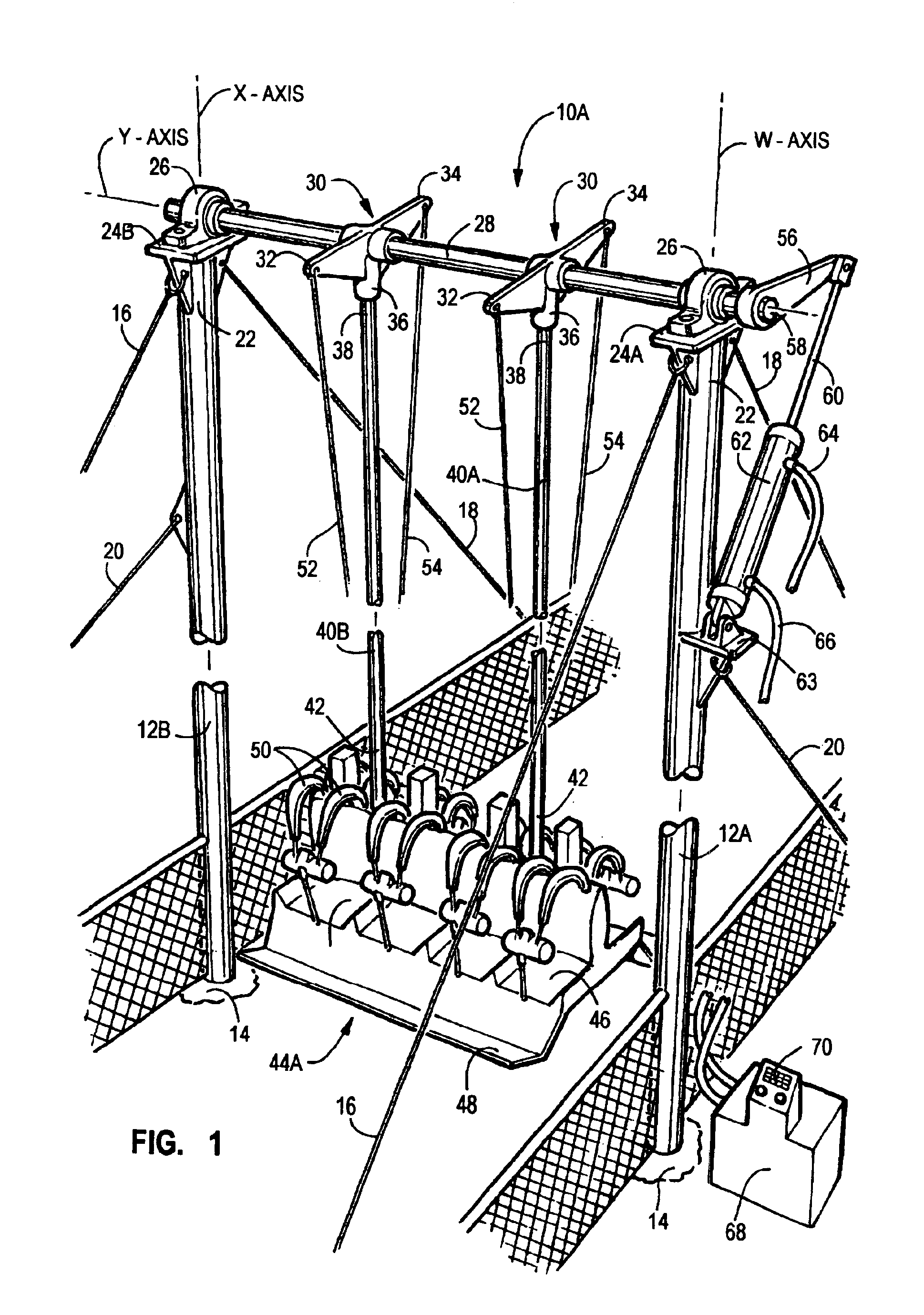
For a fuller understanding of the nature and objects of the invention, reference should be had to the following detailed description taken in conjunction with the accompanying drawings wherein similar parts of the invention are identified by like reference numerals. There is seen in FIG. 1 a perspective view of the preferred embodiment of the pneumatically actuated swing ride 10A illustrating the swing support columns 12A and 12B anchored in the ground by conventional concrete footings 14 and perpendicular to the surface of the ground on axes W and X. The swing support columns 12A and 12B are held in position by forward guy cables 16, rear guy cables 18 and side guy cables 20. At the distal upper ends 22 of the swing support columns, 12A and 12B are bearing mounting plates 24A and 24B on which pillow block bearings 26 are mounted housing the rotational shaft 28 that is parallel to the ground on Y axis. It must be understood that any form of bearing block or bushing will perform the ...


PUM


Abstract

The present invention is directed to a pneumatically actuated swing ride that has rigid swing members rotating about a shaft in a pendulum style of swinging ride. The ride operates with rigid swing members raising one or more riders in a seat platform or gondola up and then accelerates them down through an arc in the pendulum style of swinging movement. The controlled upward movement, a brief delay, and the accelerated downward movement produce weightlessness in the ride that is unmatched in the industry. The weightless effect is incurred at both ends of the arc and every time the cycle is made. By using a pneumatic cylinder, air is used as an air cushion both accelerating and decelerating the ride, giving complete control of the ride.

Description

FIELD OF THE INVENTIONThis invention relates to the field of amusement rides commonly found at carnivals, fairs and family amusement centers. More specifically this patent deals with a unique pneumatically actuated swing ride that raises the riders in an upward motion then with a delay, accelerates the riders in the downward travel of the swing faster than the natural speed occurred with the gravitational pull on the riders.BACKGROUND OF THE INVENTIONWide varieties of swing rides exist in the field of amusement rides that have many different swinging characteristics. Some of these rides use large hydraulic and electric motors operating through sophisticated gear and cable systems to facilitate an artificial swinging or tumbling action. Others use similar mechanisms to raise the riders to a position to be released, relying upon gravity and the weight of the riders to be transported through a pendulum type of swinging ride. This style of ride relies upon the natural decreasing swingin...

Claims


Application Information

Patent Timeline
Patent Type & Authority Patents(United States)
IPC IPC(8): A63G9/16A63G9/00A63G9/12A63G9/02
CPCA63G9/16A63G9/02A63G9/12
Inventor CHECKETTS, STANLEY J.
Owner S&S WORLDWIDE
Why Eureka
Try Eureka