Windbreak eye shield

a shield and windbreak technology, applied in the direction of goggles, clothing, goggles, etc., can solve the problems of unfavorable use, affecting the safety of helmet wearers, so as to achieve the effect of improving reliability in us

Inactive Publication Date: 2005-04-12
ACQUAVIVA JEAN NOEL
View PDF8 Cites 23 Cited by
  • Summary
  • Abstract
  • Description
  • Claims
  • Application Information

AI Technical Summary

Benefits of technology

The present invention aims to provide a shield type assembly offering better reliability in use.

Problems solved by technology

Such an arrangement is insufficiently sensitive to a head wind, with the result that the shield remains raised at speeds at which it ought to protect the eyes.
The whole is, moreover, cumbersome, and, what is more, disturbances to the path of the wind could cause unexpected flipping, as gusts of wind, lateral or descending, may change the anticipated direction of the wind, which is longitudinal, and raise the wings.
In the event of a gust of wind in a transverse direction, the shield is thus liable to open, even at high wind speeds.
A movement of the helmet wearer's head is liable to have the same disturbing effect.
This arrangement does not, therefore, operate reliably.

Method used


Image

  • Windbreak eye shield
  • Windbreak eye shield
  • Windbreak eye shield

Examples


Embodiment Construction

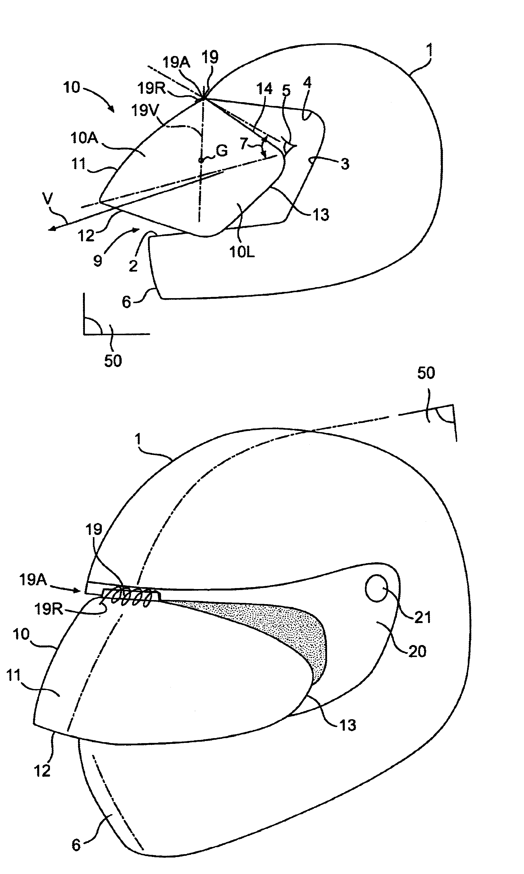
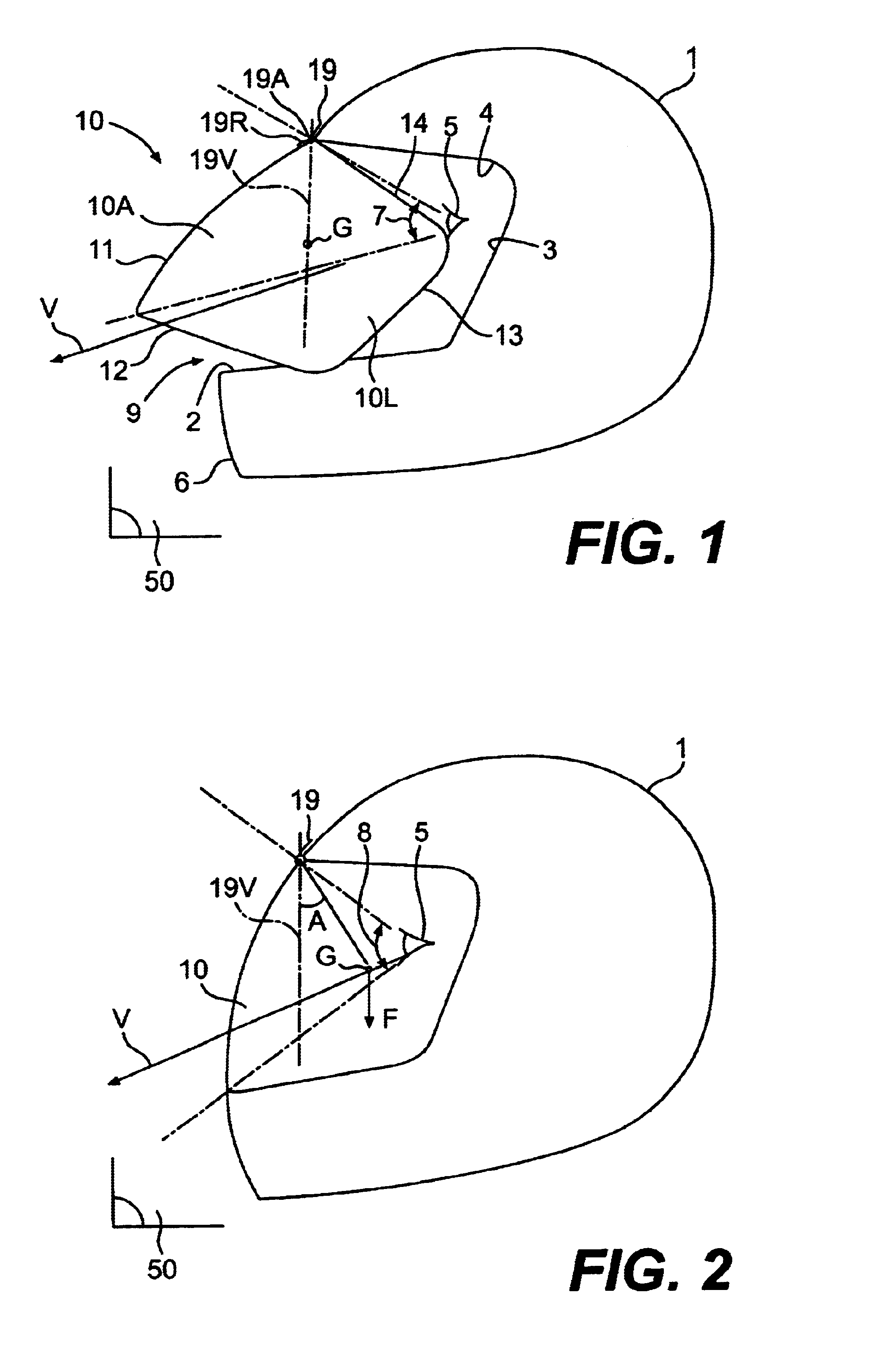
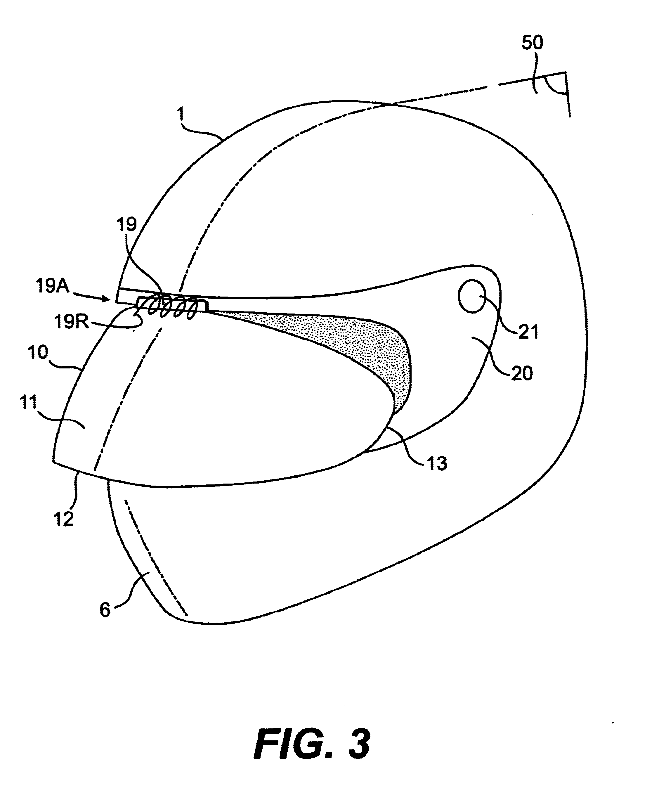
The helmet indicated by the reference 1 in FIG. 1, in this example a full-face helmet, bears a mobile windbreak eye shield 10, mainly constituted by a sheet or flap of transparent material shaped to close a conventional field of view aperture 9 of helmet 1. Shield 10 is of a shape that is intermediate between a sector of a sphere and a sector of a cylinder.

Shield 10 comprises a forward part 10A, with a front profile bearing reference number 11, and two rear lateral parts 10L, only one of which is visible here. Shield 10 is limited by a lower edge 12, two rear edges 13 and an upper edge 14, to which correspond, respectively, the following abutment edges: lower edge 2, rear edge 3 and upper edge 4 of aperture 9.

Shield 10 is mounted on helmet 1 by means of a hinge 19 which comprises a first member, fixed in the middle of the upper edge 14 of shield 10, and a second member, fixed in the middle of corresponding upper edge 4 of aperture 9. The hinge includes a pin (not shown) that provide...


PUM


Abstract

The windbreak eye shield type assembly (10) comprises members (19, 19A) for mounting the shield (10) so as to be mobile on a helmet (1), so that the shield (10) can be moved away from the line of sight, under the control of wind pressure sensing members, remaining opposed to the wind.

Description

FIELD OF THE INVENTIONThe present invention relates to windbreak eye protecting shields.Such transparent shields are fitted, for example, to helmets for the drivers of open vehicles. The shield, which is removable, forms a sort of crescent comprising two lateral ends hinging on the helmet in order for it to be brought down in front of the eyes, by a manual operation, into a functional protective position, or raised into rest position, visor-fashion.However, the fogging, or condensation, due to perspiration impairs vision, with the result that the shield has frequently to be switched from one position to another, by temporarily raising it to obtain a better view of the scene observed by observing it directly from under the raised shield, and in order to aerate the rear of the shield.These operations involving switching between the two positions are an inconvenience and even, in the present example, a danger, owing to the loss of attention that they occasion.PRIOR ARTDocument FR 2 541...

Claims


Application Information

Patent Timeline
Patent Type & Authority Patents(United States)
IPC IPC(8): A42B3/18A42B3/24
CPCA42B3/24A42B3/221A42B3/224
Inventor ACQUAVIVA, JEAN-NOEL
Owner ACQUAVIVA JEAN NOEL
Why Eureka
Try Eureka