Docking collar for a faucet having a pullout spray head

a technology of spray head and faucet, which is applied in the field of faucets, can solve the problems of only producing retention force, affecting the service life of the faucet, and increasing the stress on the spout, so as to reduce effort and force, reduce the effect of twisting and high spray head retention for

Inactive Publication Date: 2005-04-12
MOEN INC
View PDF4 Cites 120 Cited by
  • Summary
  • Abstract
  • Description
  • Claims
  • Application Information

AI Technical Summary

Benefits of technology

A further advantage of the invention is the small twist needed to undock the spray head greatly reduces the effort and force required to release the spray head. The mechanical advantage provided by the inclined plane allows a relatively high spray head retention force without causing the user to expend unusually high effort to undock the spray head. This in turn reduces the force required to undock the spray head or wand with the result that the stress on the spout is reduced as well.
is the small twist needed to undock the spray head greatly reduces the effort and force required to release the spray head. The mechanical advantage provided by the inclined plane allows a relatively high spray head retention force without causing the user to expend unusually high effort to undock the spray head. This in turn reduces the force required to undock the spray head or wand with the result that the stress on the spout is reduced as well.

Problems solved by technology

One problem with the snap finger arrangement of the prior art docking collar is the retention force is produced solely by the flexibility of the cantilevered fingers.
The high initial retention force leads to higher stresses on the spout when the user has to overcome the retention force to pull out the spray head.
This is a particular problem with high arc, gooseneck type spouts, such as in bar faucets and some kitchen faucets.
Another difficulty with high initial retention force is the potential for creating a negative first impression on prospective purchasers of the faucet.
Purchasers may try to release the wand from the spout in a floor sample faucet and decide not to purchase the faucet due to the perceived difficulty of undocking the wand.
Still another problem with prior art snap finger designs is they are susceptible to fatigue failure.

Method used


Image

  • Docking collar for a faucet having a pullout spray head
  • Docking collar for a faucet having a pullout spray head
  • Docking collar for a faucet having a pullout spray head

Examples


Embodiment Construction

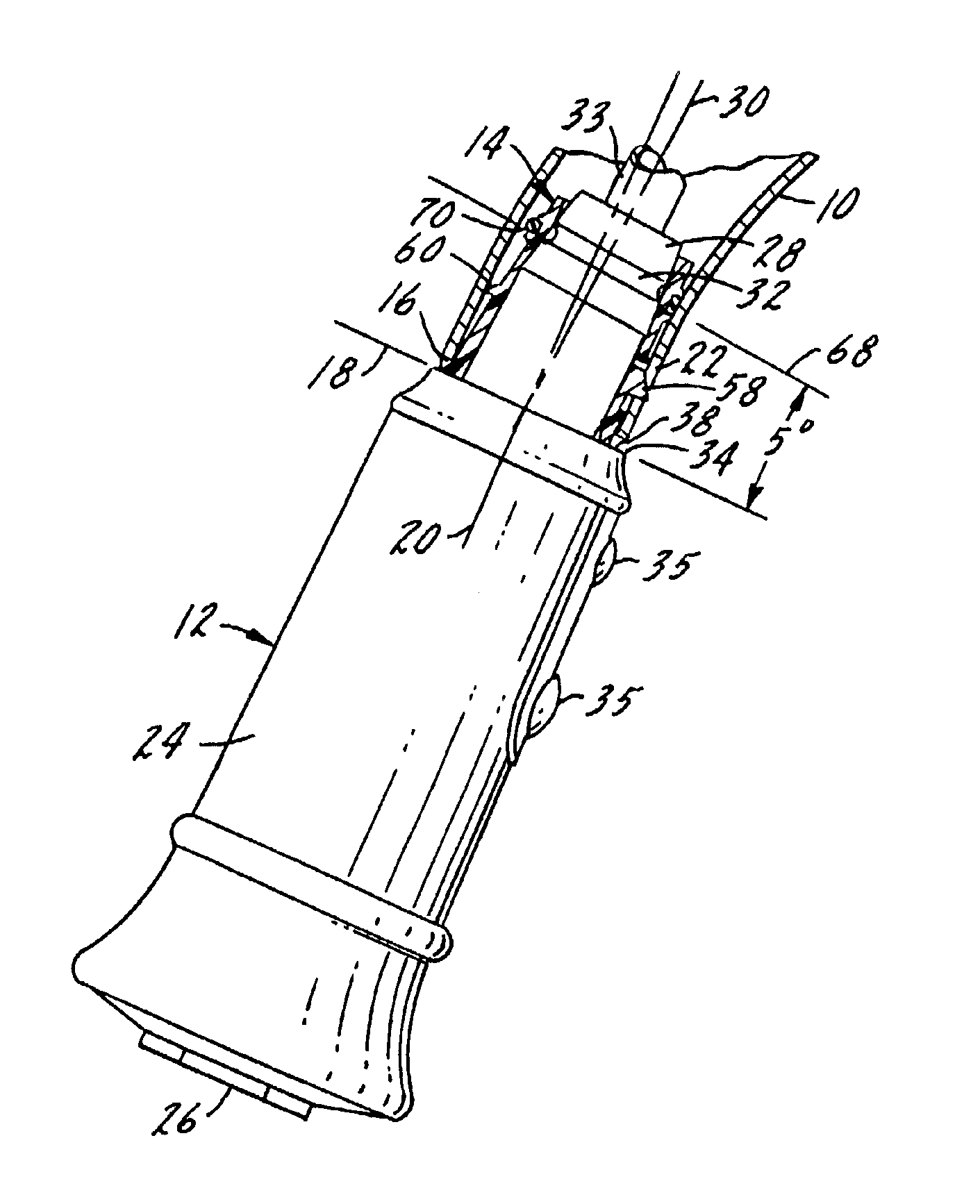
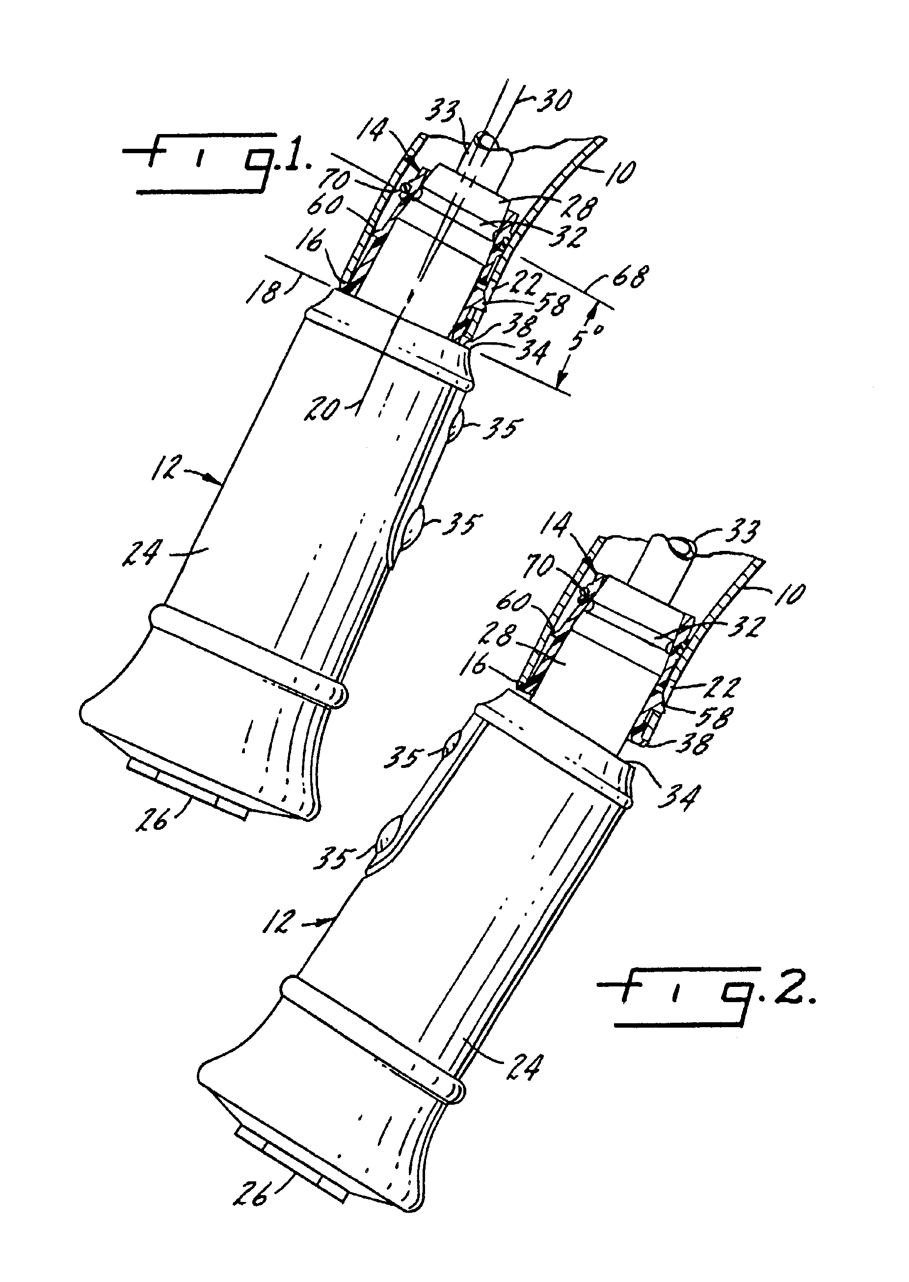
FIGS. 1 and 2 illustrate the major components of the faucet of the present invention. These include a spout 10, a pullout spray head or wand 12 and a docking collar 14. The spout 10 is a hollow, tubular member having a base, not shown, mounted on a suitable deck. The free end of the spout defines a first shoulder 16. The shoulder defines a mating plane indicated by line 18 in FIG. 1. The spout opening defines a primary axis as shown at line 20. The primary axis is normal to the mating plane. Spaced somewhat from the first shoulder 16 is an aperture 22. This aperture receives a retainer finger on the docking collar, as will be described below.

Turning now to the features of the spray head or wand 12, it includes a main body 24 which has a water discharge nozzle 26 at one end. The other end of the spray head has a male portion in the form of a hollow connecting shaft 28. The connecting shaft is generally cylindrical, although the free end may be somewhat tapered. The connecting shaft 2...


PUM


Abstract

A faucet has a spout and a pullout spray head connected to a flexible water supply tube and releasably connectable to the spout. The spout has a docking collar mounted thereon for receiving a connecting shaft of the spray head. The docking collar has an annular wall with a plurality of U-shaped slots which define a plurality of cantilevered snap fingers. Each snap finger includes a projection that fits into a groove in the connecting shaft when the spray head is docked. An elastomeric O-ring surrounds the annular wall at a point where the O-ring engages the snap fingers to bias them toward the groove. Ridges on the exterior surface of the wall retain the O-ring in place. The spout and docked spray head have parallel shoulders that define a mating plane. The projections and groove define a retaining plane. The mating plane is not parallel to the retaining plane such that rotation of the spray head about an axis normal to the mating plane will cause the projections to release from the groove.

Description

BACKGROUND OF THE INVENTIONThis invention relates to faucets of the type having a pullout spray head and is particularly concerned with an improved docking collar. The docking collar is fixed at or near the end of a spout for mating with a pullout spray head or wand to releasably hold or mount the spray head to the spout. The docking collar of the prior art typically includes a plurality of cantilevered, flexible snap fingers which are engageable with recesses or the like in a portion of the pullout spray head which fits into the collar. The snap fingers of the prior art collar rely on the inherent resiliency of the plastic material of which the collar is made to produce a retaining force. This retaining force, while enough to hold the wand on the spout, can be overcome when a user wishes to release the wand from the spout. Release of the spray head is achieved by simply pulling outwardly or downwardly on the spray head until the snap fingers are forced to flex out of the mating rec...

Claims


Application Information

Patent Timeline
Patent Type & Authority Patents(United States)
IPC IPC(8): E03C1/04
CPCE03C1/0404E03C2001/0415
Inventor MALEK, MICHAEL L.TUCKER, W. RANDALL
Owner MOEN INC
Why Eureka
Try Eureka