
Volume filling mechanical structures for modifying crash deceleration pulse

a mechanical structure and deceleration pulse technology, applied in the direction of shock absorbers, elastic dampers, roofs, etc., can solve the problems of unstable contraction space, low force level, and inability to use other uses of occupied contraction spa

Inactive Publication Date: 2005-04-12
GM GLOBAL TECH OPERATIONS LLC
View PDF19 Cites 13 Cited by
  • Summary
  • Abstract
  • Description
  • Claims
  • Application Information

AI Technical Summary

Benefits of technology

The present invention is a mechanical, active dedicated crash energy management structure that provides modification of crash deceleration pulse. It has a small dormant volume and only assumes a larger deployed volume just prior to or in response to a crash. The structure includes a honeycomb brick made of expanded honeycomb material that occupies empty space adjacent to operational clearances, serviceability, and repair functions. The honeycomb brick is placed in the engine compartment or other spaces that need to be left open for various reasons. It is designed to expand in the transverse plane parallel to the crash axis upon activation by an active or passive activation mechanism. The expanded honeycomb has excellent crash energy management capabilities, but it can also be compressed back to the dormant state for manual resetting in case of a serious crash. The invention provides a dedicated crash energy management structure that has a small dormant volume and can timely expand into a much larger deployed volume for managing the energy of an expectant crash pulse.

Problems solved by technology

Since these passive crash energy management structures occupy a maximum volume in the uncrushed / unstroked, initial state, they inherently occupy vehicular space that must be dedicated for crash energy management—the contraction space being otherwise unstable.
This occupied contraction space is not available for other uses, including functions such as vehicle component inspection, servicing and repair.
Downsides of such systems include low force levels and low ratios of crush force to added mass due to the lack of mechanical rigidity of these systems.

Method used


Image

  • Volume filling mechanical structures for modifying crash deceleration pulse
  • Volume filling mechanical structures for modifying crash deceleration pulse
  • Volume filling mechanical structures for modifying crash deceleration pulse

Examples


Embodiment Construction

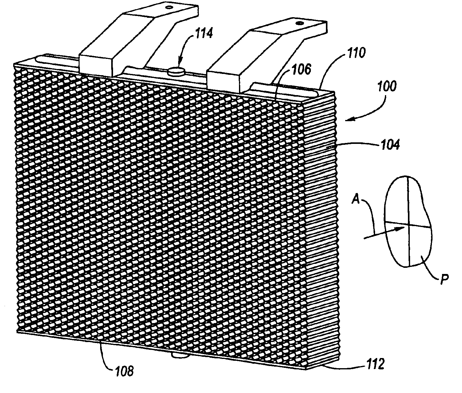
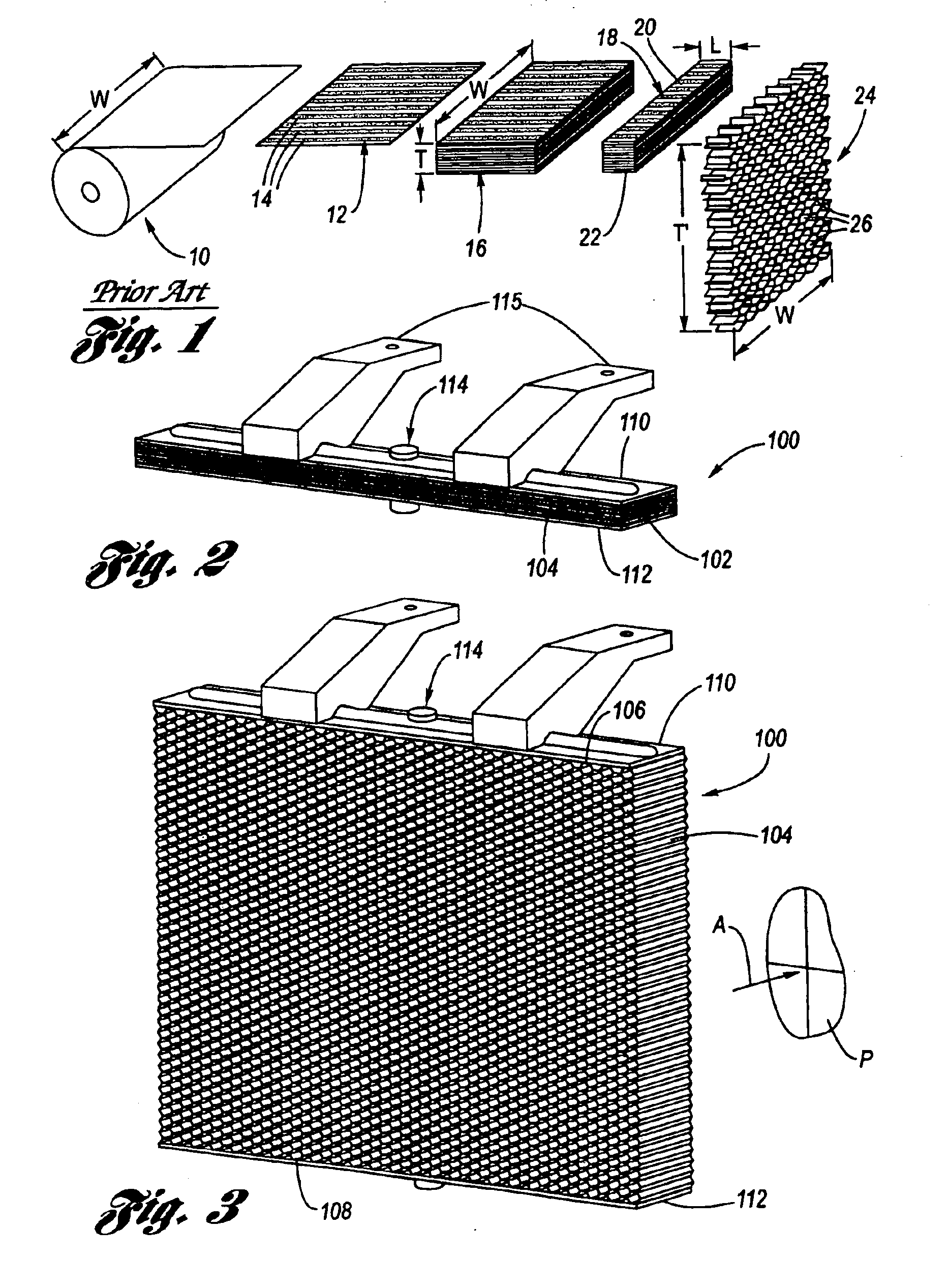
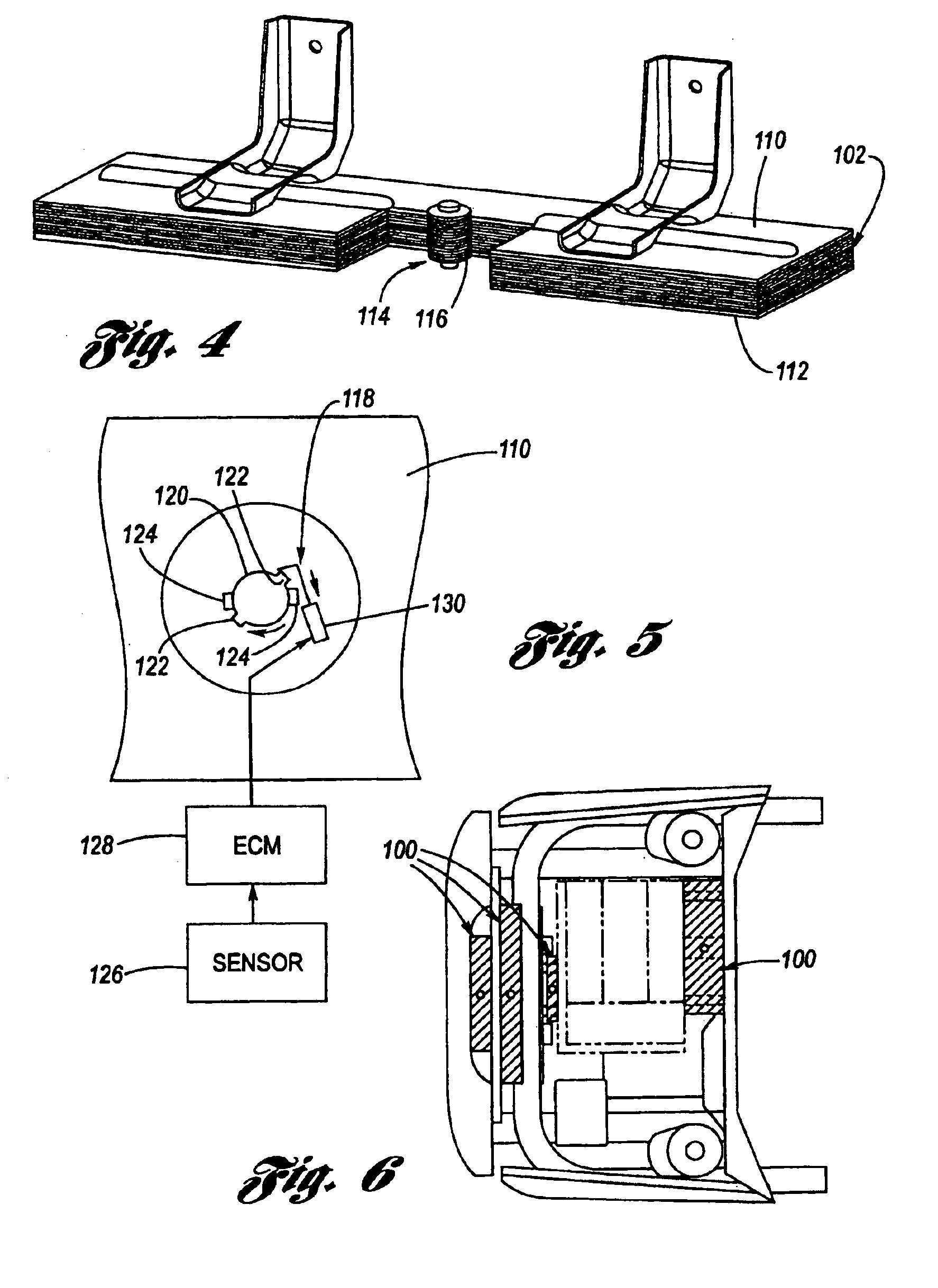
Referring now to the Drawing, FIGS. 2 through 9 depict a most preferred embodiment of an active dedicated crash energy management structure 100 according to the present invention.

A honeycomb brick 102 composed of a honeycomb celled material 104 is provided, as for example according to a method of manufacture utilized to provide HOBE® bricks, as discussed hereinabove. The honeycomb brick 102 is not expanded such that it is at its most compacted state. Attached (such as for example by an adhesive) to the upper and lower faces 106, 108 of the honeycomb brick 102 are respective end caps 110, 112. The end caps 110, 112 are rigid and serve as guide members for defining the configuration of the honeycombed cell material 104 between a dormant state as shown at FIG. 2 and a deployed state as shown at FIG. 3.

The end caps 110, 112 need not necessarily be planar. Indeed, they do not need to have the same shape or size, but for a minimum unexpanded volume the end caps should have the same size a...


PUM


Abstract

A mechanical, active crash pulse management structure for providing modification of crash pulse, wherein the structure has a dormant (initial) state volume, but then in the event of a crash, timely expands into a much larger deployed volume for providing management of an expectant crash energy. The preferred crash energy management structure is a before expansion honeycomb celled material brick, wherein expansion of the honeycomb brick is in a plane transverse to the cellular axis of the cells thereof, and crash crush is intended to be parallel to the cellular axis. In the event of a crash, either an active or passive activation mechanism is provided for causing expansion of honeycomb celled material.

Description

TECHNICAL FIELDThe present invention relates to structures used for modifying a vehicle deceleration pulse (crash pulse), and more particularly to mechanical structures which are volumetrically reconfigurable such as to occupy a small volume when in a dormant state and then rapidly expand to a larger volume in a deployed state when needed for providing crash pulse modification.BACKGROUND OF THE INVENTIONA vehicle, in addition to the inherent crush characteristics of its structure, may have dedicated crash energy management structures. Their function is exclusively to dissipate energy in the event of a crash. Such dedicated structures have predetermined crush characteristics which contribute to the resulting deceleration pulse to which the occupants are subjected.In the vehicular arts there are two known types of such dedicated crash energy management structures: those which are passive, and those which are active.An example of a passive dedicated crash energy management structure is...

Claims


Application Information

Patent Timeline
Patent Type & Authority Patents(United States)
IPC IPC(8): B60R19/00F16F7/12
CPCB60R19/00F16F7/121B60R2021/0004B60R2019/007
Inventor BROWNE, ALAN LAMPEJOHNSON, NANCY L.
Owner GM GLOBAL TECH OPERATIONS LLC
Learn More