Detachable lamp assembly device

a technology of assembly device and lamp, which is applied in the direction of lighting support device, coupling device connection, lighting and heating apparatus, etc., can solve the problems of high cost, inconvenient assembly, and tedious assembly work

Inactive Publication Date: 2005-04-12
WU WEN CHANG
View PDF2 Cites 3 Cited by
  • Summary
  • Abstract
  • Description
  • Claims
  • Application Information

AI Technical Summary

Benefits of technology

Accordingly, the primary object of the present invention is to provide a detachable lamp assembly device comprising a lamp seat firmly secured to a lateral side of a wire winding box, and a lamp rod inserted into the lamp seat. A lateral side of the wire winding box has a via hole and a portion of the lamp seat coupled to the via hole of the wire winding box has a penetrating hole. Two sides of the lamp seat are formed with embedding holes penetrated axially on a surface of the lamp seat for positioning the lamp rod. A front end of the lamp rod is exactly inserted into an end portion in the inserting seat of the lamp seat. A portion of the lamp rod coupled to the embedding holes of the lamp seat is formed with a receiving groove. A limiting reed is locked to the receiving groove. A buckling elastic piece is locked to the limit groove. Two sides of the limiting reed are installed with buckles; and the buckles slightly protrude from an edge of the receiving groove. An edge of each buckle of the reed is installed with a bank of stepped surface. Thus, after the lamp rod is inserted into the lamp seat, the lamp rod is prevented from being out of the lamp seat. Thereby, a user can assemble the lamp rod by inserting it into the lamp seat easily. Moreover, the lamp is detachable for storage and transfer with a smaller volume.

Problems solved by technology

Moreover, the assembly work is tedious and thus it is unsuitable for being assembled by the users themselves.
Thereby, the cost is high and a larger space is necessary for transfer and storage.

Method used


Image

  • Detachable lamp assembly device
  • Detachable lamp assembly device
  • Detachable lamp assembly device

Examples


Embodiment Construction

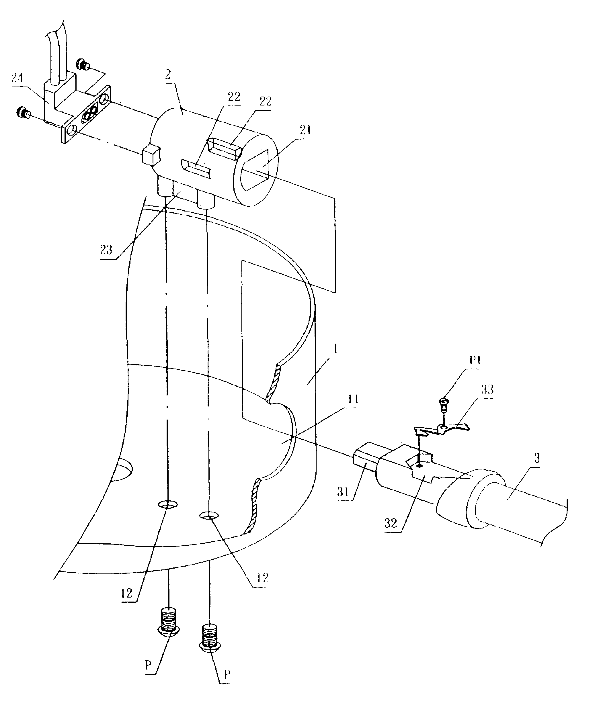
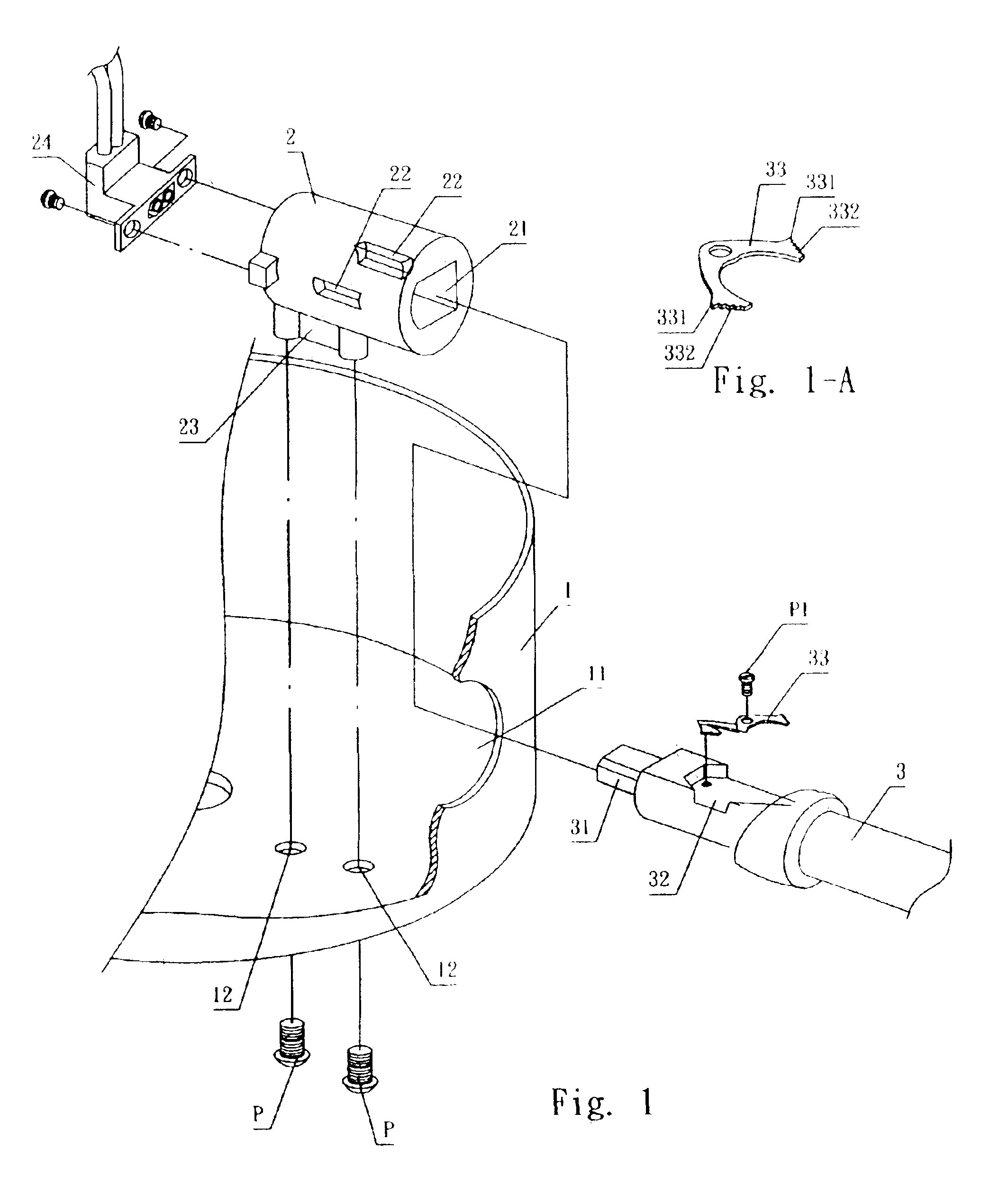
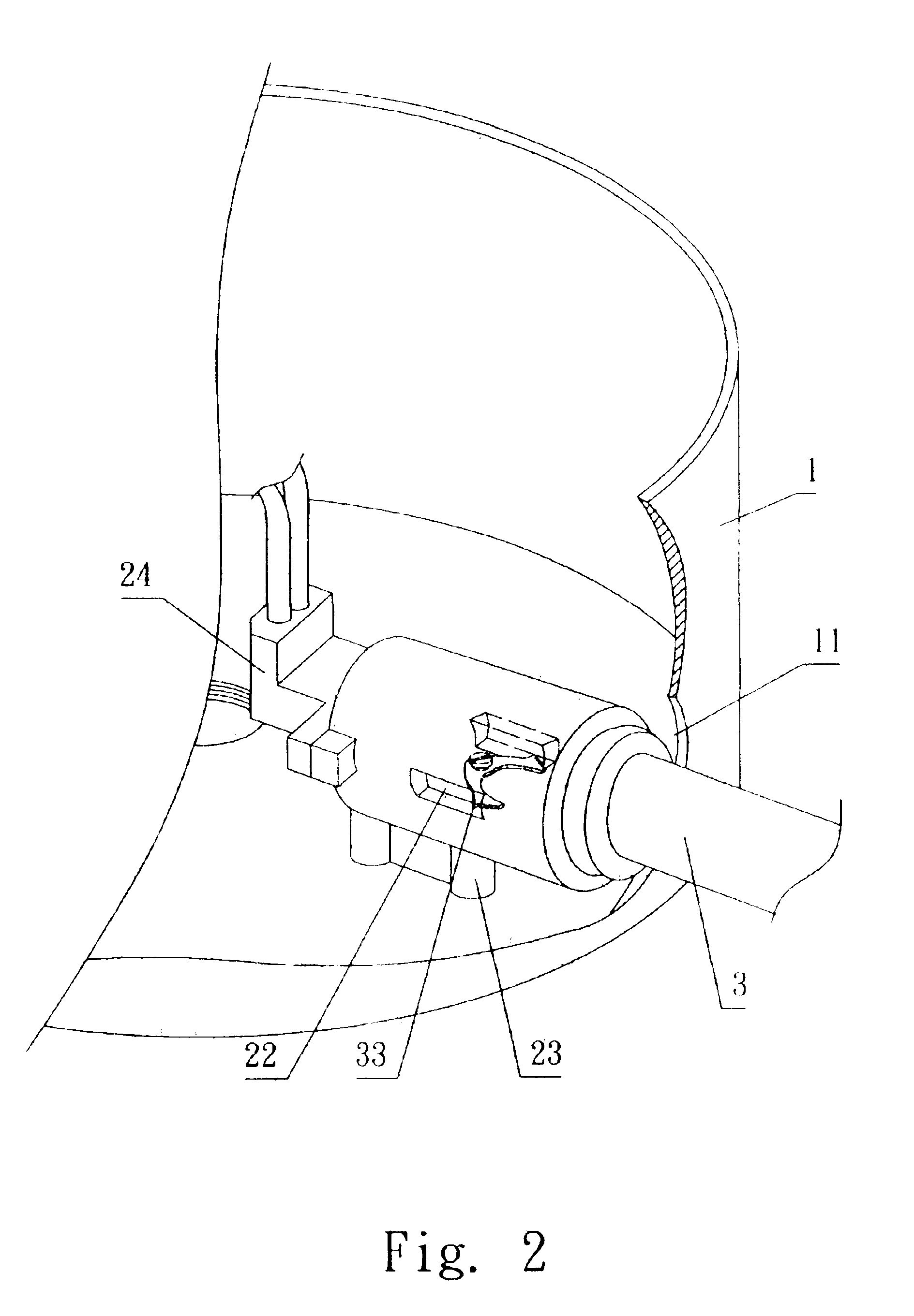
Referring to FIGS. 1 and 2, the device of the present invention is illustrated. The present invention includes a lamp seat 2 firmly secured to a lateral side of a wire winding box 1, and a lamp rod 3 inserted into the lamp seat 2.

A lateral side of the wire winding box 1 has a via hole 11 and a bottom of the wire winding box 1 coupled to the lamp seat 2 has through holes 12 for being passed by a stud P so as to lock the lamp seat 2 to a predetermined positioned.

A portion of the lamp seat 2 coupled to the via hole 11 of the wire winding box 1 has a penetrating hole 21. One side of the penetrating hole 21 has an elliptical shape, and the other three sides of the penetrating hole 21 have a rectangular shape. Thereby, when the lamp rod 3 is inserted into the lamp seat 2, the lamp rod 3 cannot rotate. Two sides of the lamp seat 2 are formed with embedding holes 22 penetrated axially on a surface of the lamp seat 2 for positioning the lamp rod 3. A lower side of the lamp seat 2 protruded w...


PUM


Abstract

A detachable lamp assembly device is disclosed. A limiting reed is locked to the receiving groove. A buckling elastic piece is locked to the limit groove. Two sides of the limiting reed are installed with buckles; and the buckles slightly protrude from an edge of the receiving groove. An edge of each buckle of the reed is installed with a bank of stepped surface. Thus, after the lamp rod is inserted into the lamp seat, the lamp rod is prevented from being out of the lamp seat. Thereby, a user can assemble the lamp rod by inserting it into the lamp seat easily. Moreover, the lamp is detachable for storage and transfer with a smaller volume.

Description

BACKGROUND OF THE INVENTIONThe present invention relates to lamp assembly devices, and particularly to a detachable lamp assembly device. By the design of the present invention, a user can assemble the lamp rod by inserting it into the lamp seat easily; thus, the lamp is detachable for storage and transfer with a smaller volume.The prior art buckling structures of lamps, such as wall lamps, seat lamps, or stand lamps, are assembled by screwing studs with nuts. Not only collision events easy occur, but also the locking tools (for example, spanners, openers, etc.) are necessary in assembly. In assembly, the wires will expose so as to generate electric shock. Moreover, the assembly work is tedious and thus it is unsuitable for being assembled by the users themselves. Thus generally, the wire winding box is assembled with the inserting rod before sale. Thereby, the cost is high and a larger space is necessary for transfer and storage.SUMMARY OF THE INVENTIONAccordingly, the primary obje...

Claims


Application Information

Patent Timeline
Patent Type & Authority Patents(United States)
IPC IPC(8): F21V23/06F21V21/02F21S8/04F21S8/06F21V23/00
CPCF21S8/065F21V23/06F21V21/02
Inventor WU, WEN-CHANG
Owner WU WEN CHANG
Why Eureka
Try Eureka