Multi-band horn antenna using corrugations having frequency selective surfaces

a frequency selective surface and multi-band technology, applied in the direction of horns, simultaneous aerial operations, waveguide horns, etc., can solve the problems of limiting the operational bandwidth of a waveguide, other modes with different field configurations can occur unintentionally or deliberately, and the operational frequency and bandwidth of conventional waveguides are limited

Active Publication Date: 2005-04-12
NORTH SOUTH HLDG
View PDF11 Cites 44 Cited by
  • Summary
  • Abstract
  • Description
  • Claims
  • Application Information

AI Technical Summary

Problems solved by technology

At higher frequencies, higher modes are supported and will tend to limit the operational bandwidth of a waveguide.
Other modes with different field configurations can occur unintentionally or can be caused deliberately.
Since waveguides are generally designed to have a static geometry, the operational frequency and ba...

Method used


Image

  • Multi-band horn antenna using corrugations having frequency selective surfaces
  • Multi-band horn antenna using corrugations having frequency selective surfaces
  • Multi-band horn antenna using corrugations having frequency selective surfaces

Examples


Embodiment Construction

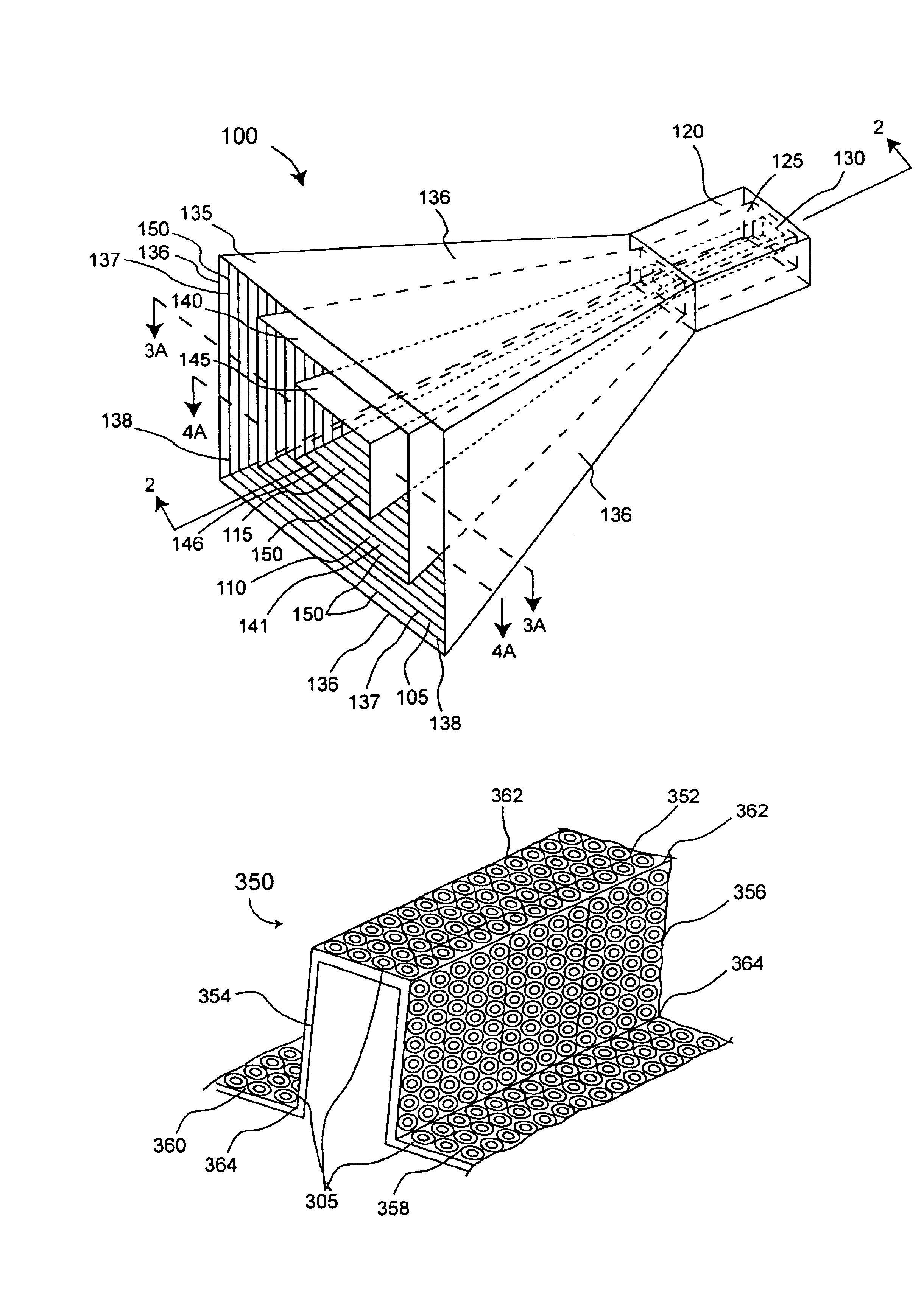
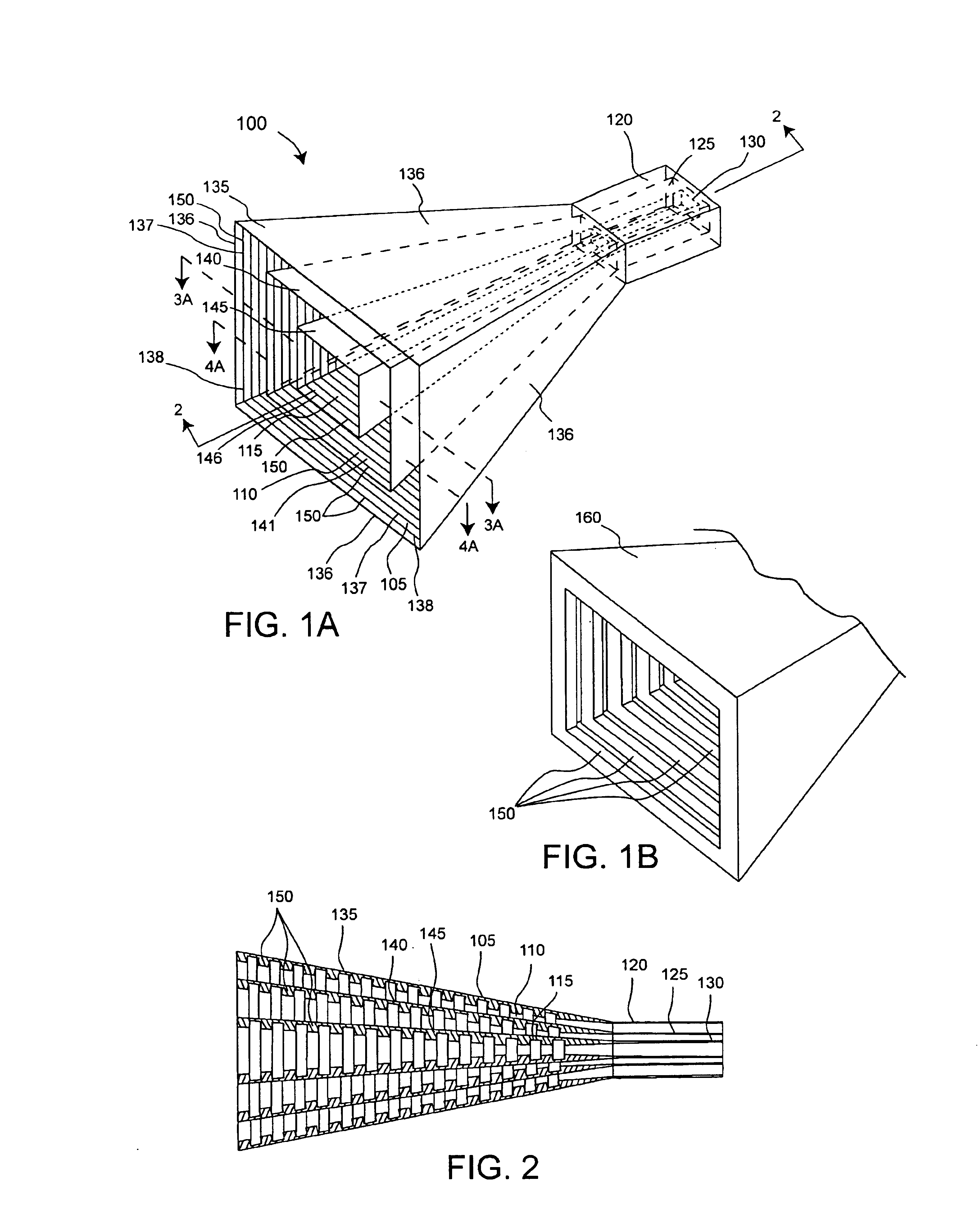
The present invention concerns a multi-band horn antenna (multi-band horn) 100 which includes corrugations having frequency selective surfaces (FSS's), an example of which is shown in FIG. 1A. A cross sectional view of the multi-band horn antenna 100 taken along section lines 2—2 is shown in FIG. 2. Although the multi-band horn 100 shown has a pyramidal shape, the skilled artisan will appreciate that horns are available in a number of different shapes and the invention is not so limited. For example, the horn can be cylindrical, conical, parabolic, or any other suitable shape.

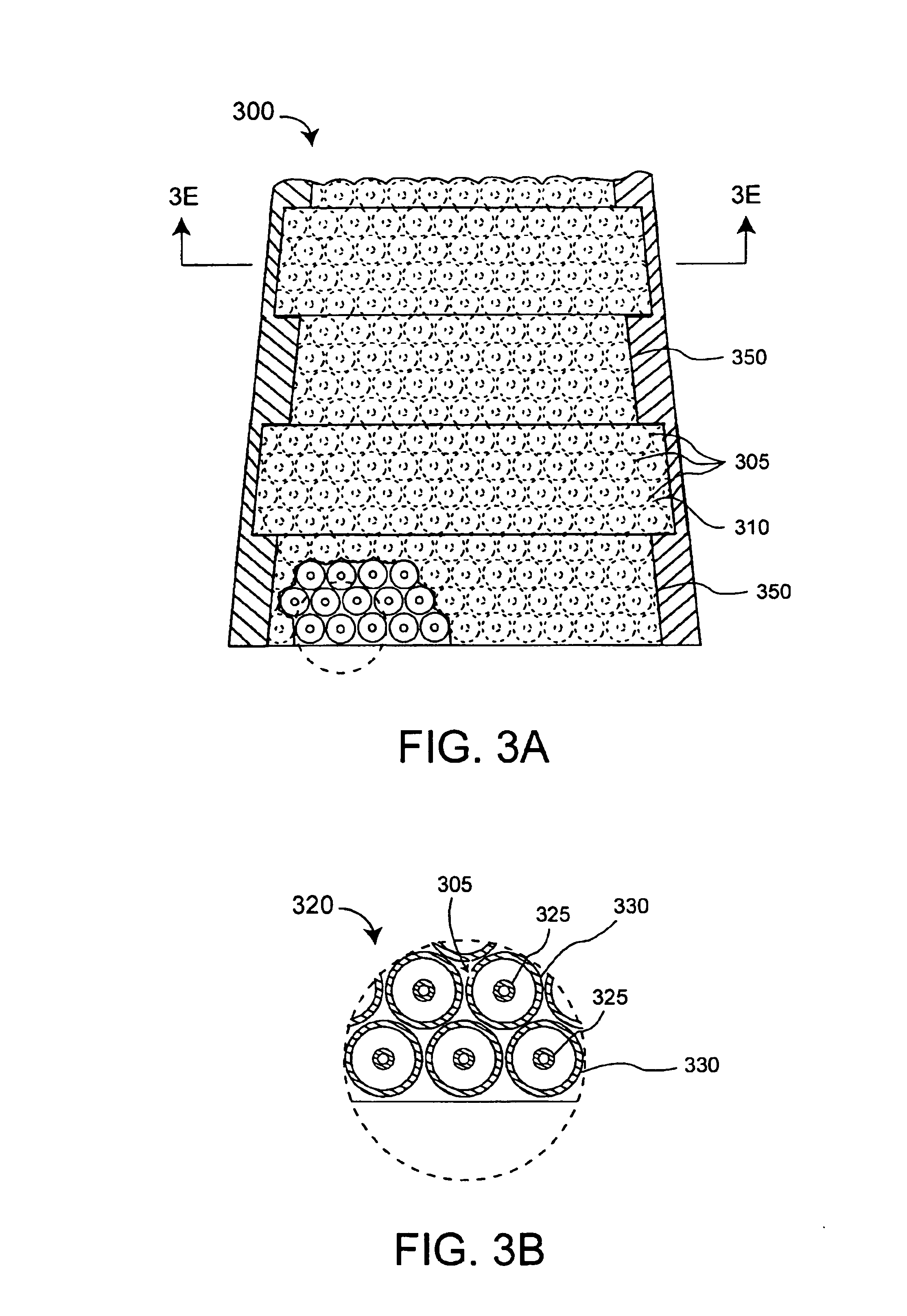
Making reference to FIGS. 1A and 2, the multi-band horn 100 can include a first horn section 105 and a second horn section 110 which is concentrically disposed within the first horn section 105. At least one of the horn sections 105, 110 can be a corrugated horn which includes circumferential grooves, or corrugations 150, along the interior walls of the antenna. An enlarged view of an exemplary horn section 160...


PUM


Abstract

An antenna (100) for microwave radiation including a first horn (135) which includes a plurality of corrugations (150). At least one of the corrugations (150) is formed of a frequency selective surface (FSS) (138). The FSS has a plurality of FSS elements (305) coupled to at least one substrate (310). The substrate (310) can define a first propagation medium such that an RF signal having a first wavelength in the first propagation medium can pass through the FSS (300). The FSS (300) is coupled to a second propagation medium such that in the second propagation medium the RF signal has a second wavelength which is at least twice as long as a physical distance between centers of adjacent FSS elements (305).

Description

BACKGROUND OF THE INVENTIONStatement of the Technical FieldThe inventive arrangements relate generally to methods and apparatus for horn antennas, and more particularly to horn antennas which can operate in multiple frequency bands.Description of the Related ArtConventional electromagnetic waveguides and horn antennas are well known in the art. A waveguide is a transmission line structure that is commonly used for microwave signals. A waveguide typically includes a material medium that confines and guides a propagating electromagnetic wave. In the microwave regime, a waveguide normally consists of a hollow metallic conductor, usually rectangular, elliptical, or circular in cross section. This type of waveguide may, under certain conditions, contain a solid, liquid, liquid crystal or gaseous dielectric material.In a waveguide, a “mode” is one of the various possible patterns of propagating or standing electromagnetic fields. Each mode is characterized by frequency, polarization, elec...

Claims


Application Information

Patent Timeline
IPC IPC(8): H01Q13/00H01Q5/00H01Q5/47H01Q13/02
CPCH01Q5/47H01Q13/025
Inventor ZARRO, MICHAEL S.DELGADO, HERIBERTO J.KILLEN, WILLIAM D.
Owner NORTH SOUTH HLDG
Why Eureka
Try Eureka