Sampling end for fiber optic probe

a fiber optic probe and end-end technology, applied in the field of fiber optic probe devices, can solve the problems of inconvenient use, inconvenient assembly of components of the probe, and potential contamination of conventional fiber optic probes,

Inactive Publication Date: 2005-04-12
C TECH
View PDF43 Cites 32 Cited by
  • Summary
  • Abstract
  • Description
  • Claims
  • Application Information

AI Technical Summary

Benefits of technology

In another embodiment, the sampling end can be used without a reflective surface and the outer side of the optical window of the elongated tube can be coated with a chemical composition which may be reactive with a component of a fluid medium. L

Problems solved by technology

Conventional fiber optic probes, however, have some drawbacks.
One such drawback is the potential for contamination which can occur when a probe from one solution is not completely cleaned and then inserted into another solution.
Another problem associated with conventional fiber o

Method used


Image

  • Sampling end for fiber optic probe
  • Sampling end for fiber optic probe
  • Sampling end for fiber optic probe

Examples


Embodiment Construction

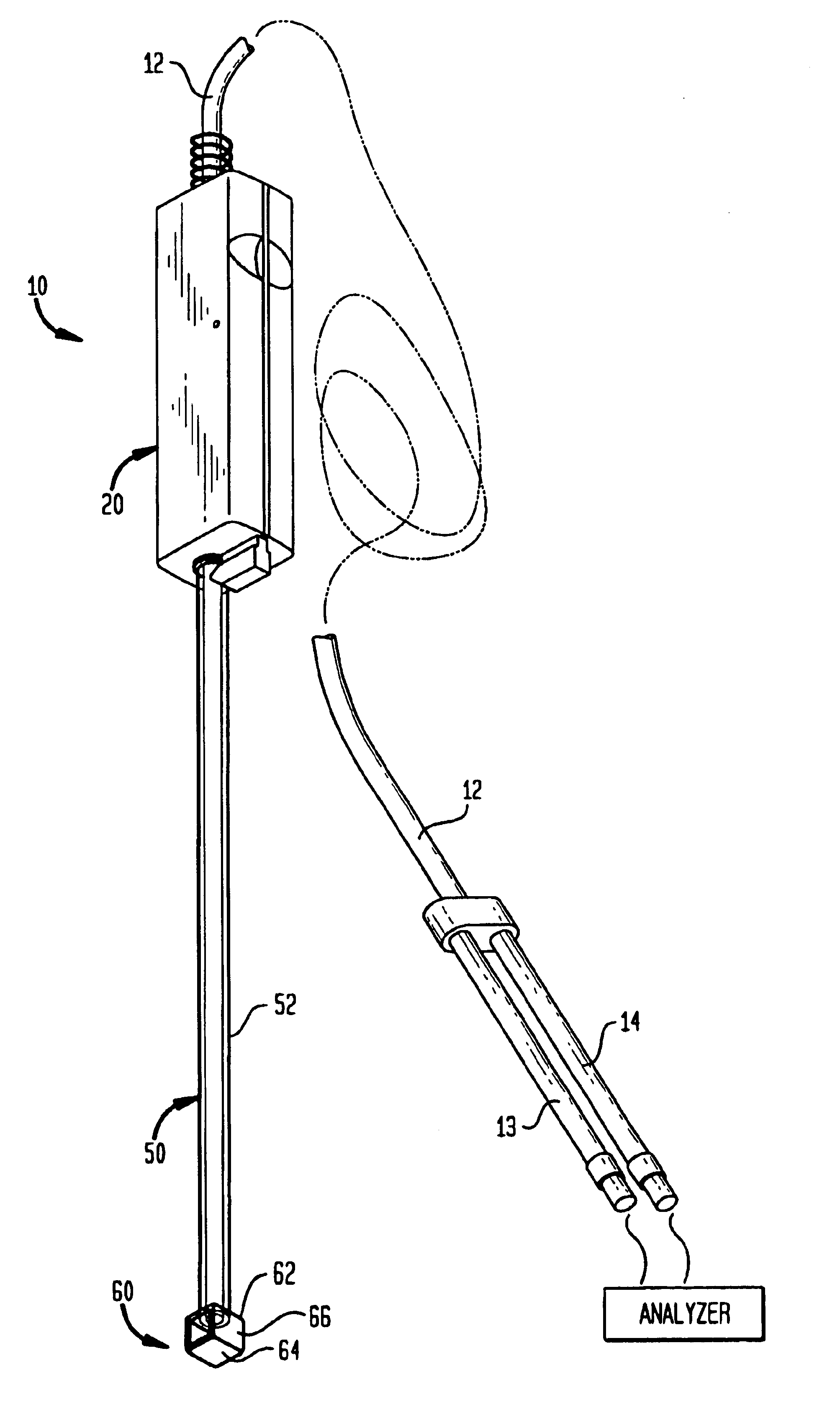
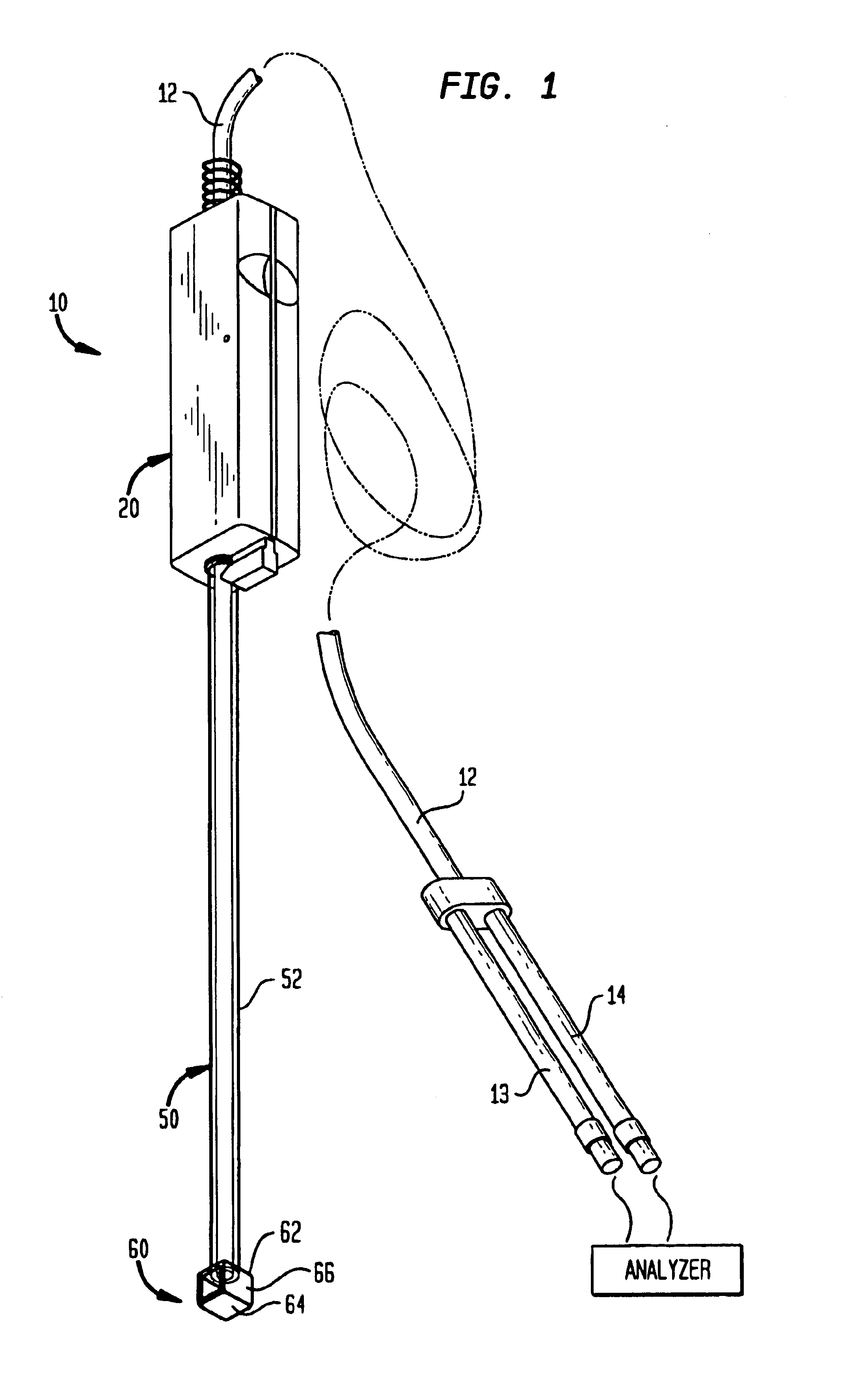
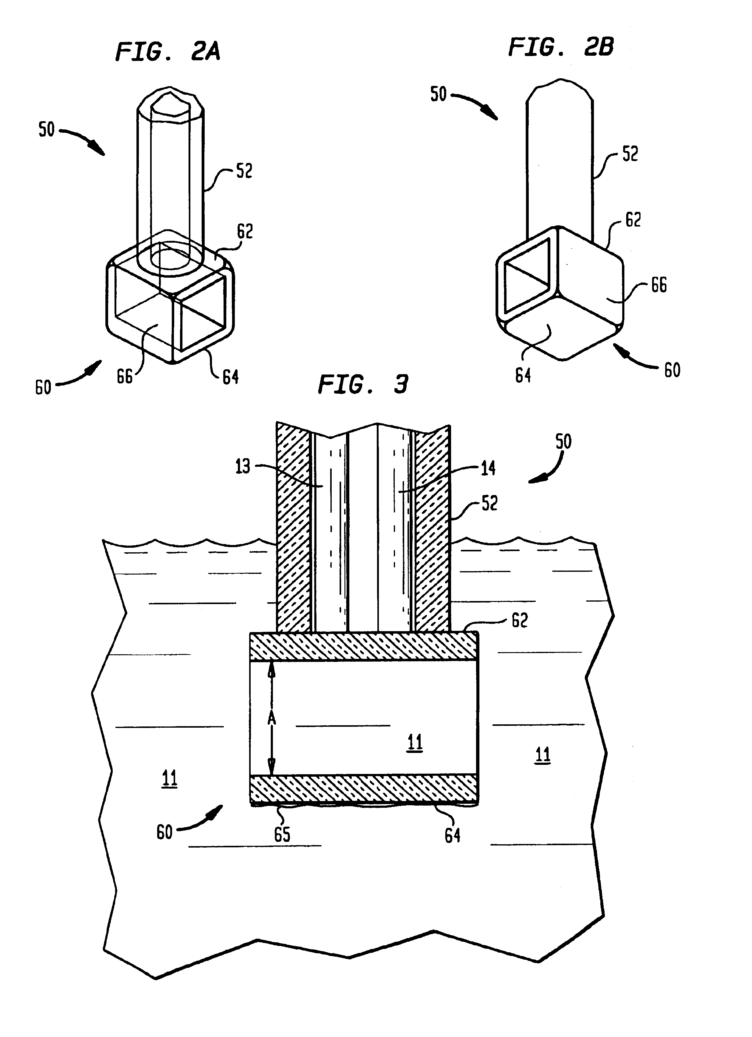
The present invention relates to a fiber optic probe device having a sampling end positionable over optical fibers. The sampling end may be attachable to a probe handle or to the optical fibers. The sampling end comprises an elongate tube having an open end and a closed end. The optical fibers extend from the handle, through the open end of the sampling end to abut the closed end of the sampling end. The open end of the sampling is preferably releasably attached to the handle, or the optical fibers. The sampling end can be attached, used, released and replaced. It can be discarded after use or re-used. The closed end comprises an optical window which allows for light to pass into and out of the optical fibers. A sample chamber can be positioned at the closed end of the sampling end. As will be discussed, in an alternative embodiment, the sampling end can be associated with a vessel, pipe or other fluid container and the optical fibers inserted thereinto for taking measurements.

FIG. ...


PUM


Abstract

A fiber optic probe device having a sampling end positionable over optical fibers is provided. The sleeve could be releasably attached to the fiber optic probe device. The sampling end can be discarded after use, or re-used. A sample chamber including a reflective surface can be formed at the distal end of the sampling end.

Description

BACKGROUND OF THE INVENTION1. Field of the InventionThe present invention relates to a fiber optic probe device and more particularly to a fiber optic probe device having a sampling end positionable over the optical fibers.2. Related ArtFiber optic probes have long been used to measure the properties of solutions. Such probes use optical fibers to send out light to interact with the solution. The light is then picked up by the optical fibers. This received light includes information about the characteristics of the solution. Fiber optic probes can be used in various applications including manufacturing processes, medical applications, remote measurements in harsh environments, monitoring ground water flow, etc.One type of fiber optic probe includes transmitting and receiving optical fibers that extend side by side down the probe. One of the fibers terminates while the other extends beyond the first fiber and then back up so that it is in a facing relation with the first fiber. There...

Claims


Application Information

Patent Timeline
IPC IPC(8): G01N21/85
CPCG01N21/8507G01N2021/8528
Inventor SALERNO, MARKHARRISON, CRAIG D.NIR, ISHAIDEWAAL, HANSVIEIRA, MARIO
Owner C TECH
Why Eureka
Try Eureka