
Dynamic spray system

a technology of dynamic spraying and spraying, which is applied in the direction of lighting and heating equipment, instruments, and domestic cooling equipment, etc., can solve the problems of less effective cooling of semiconductors, and failure of weaker semiconductors during testing, so as to reduce the cost of implementation and operation, reduce the cost of operation, and reduce the effect of burn-in tim

Inactive Publication Date: 2005-04-19
PARKER INTANGIBLES LLC
View PDF70 Cites 43 Cited by
  • Summary
  • Abstract
  • Description
  • Claims
  • Application Information

AI Technical Summary

Benefits of technology

[0013]In view of the foregoing disadvantages inherent in the known types of semiconductor burn-in systems now present in the prior art, the present invention provides a new dynamic spray system construction wherein the same can be utilized for effectively thermally managing electronic components.

Problems solved by technology

By applying increased voltages and temperatures to a semiconductor, the weaker semiconductors will fail during testing.
For example, a poor thermal management system can produce a junction temperature spread from 75° to 125° Celsius resulting in a low median junction temperature, longer burn-in time and higher associated burn-in costs.
During class test, non-uniform heating of the semiconductors typically occurs.
A further problem with conventional thermal management systems is that they are inefficient, complex, costly to implement and costly to operate.
A further problem with conventional thermal management systems is that the resulting junction temperature spreads result in relatively long burn-in times of the semiconductor devices.
Another problem with conventional thermal management systems is that they require significant amounts of power to operate.

Method used


Image

  • Dynamic spray system
  • Dynamic spray system
  • Dynamic spray system

Examples


Embodiment Construction

A. Overview

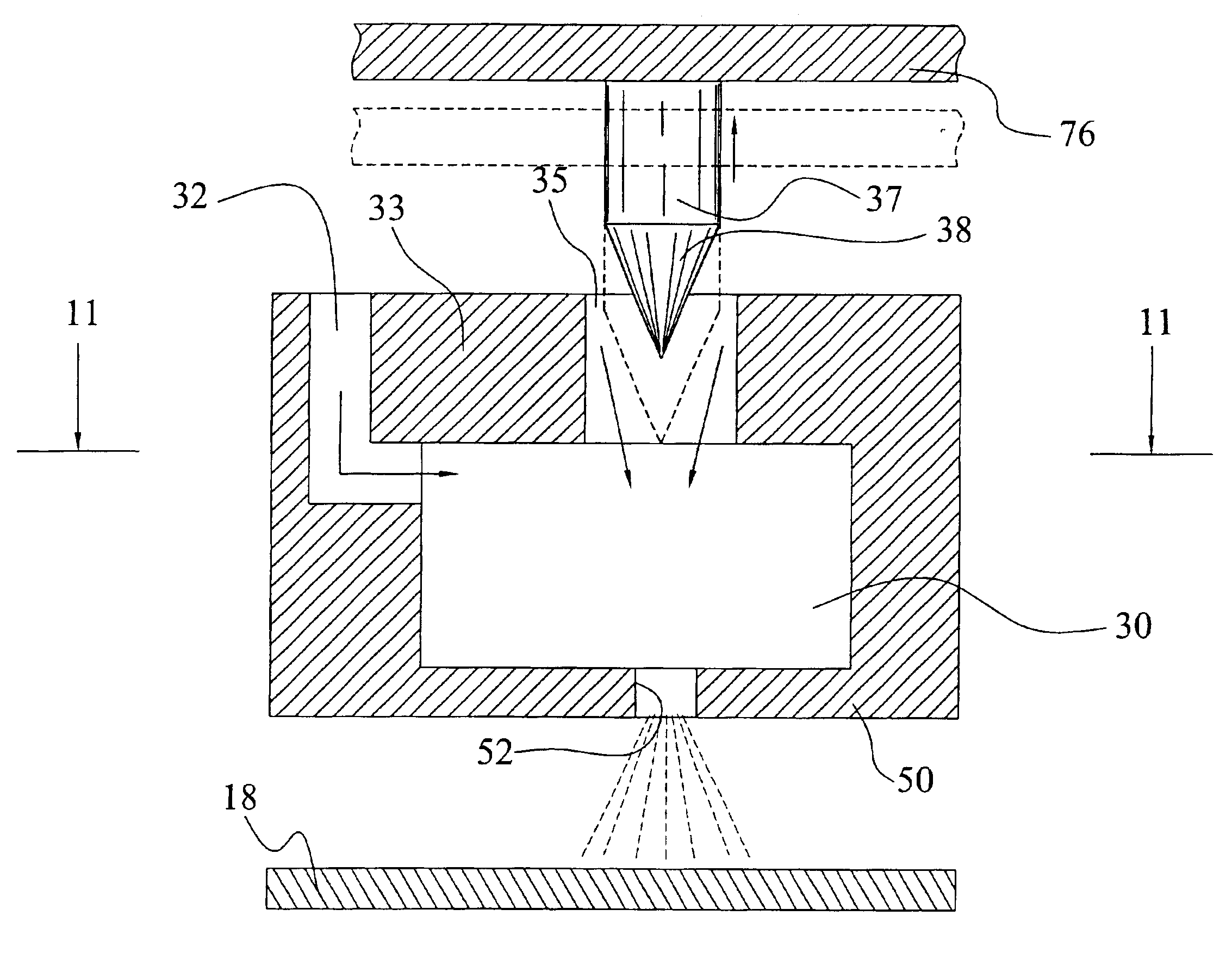
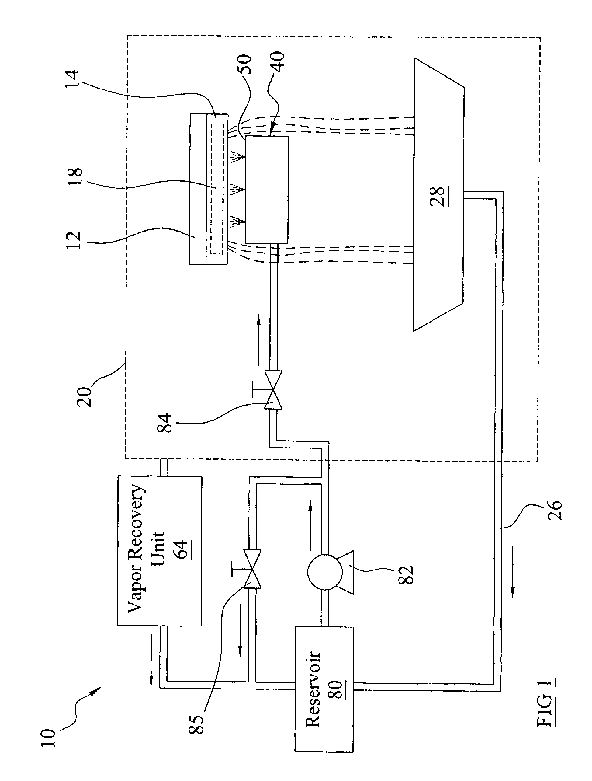
[0044]Turning now descriptively to the drawings, in which similar reference characters denote similar elements throughout the several views, FIGS. 1 through 12 illustrate a dynamic spray system 10, which comprises one or more spray units 40 each having a housing structure 42, a first portion 50, a first orifice 52 within said first portion 50 fluidly connected to a swirl chamber 30, a main jet 35 fluidly connected to the swirl chamber 30, a plunger 37 movably positioned within the main jet 35 for adjusting fluid flow through the main jet 35, and at least one swirl inlet 32 fluidly connected to the swirl chamber 30 for generating a fluid swirl effect within the swirl chamber 30. The main jet 35 is preferably aligned with the first orifice 52 for dispersing a relatively narrow spray pattern from the first orifice 52 when the fluid flow is increased through the main jet 35. The spray pattern is broadened when the fluid flow through the main jet 35 is decreased.

B. Spray Enclo...


PUM


Abstract

A dynamic spray system for effectively thermally managing electronic components. The dynamic spray system includes one or more spray units each having a housing structure, a first portion, a first orifice within said first portion fluidly connected to a swirl chamber, a main jet fluidly connected to the swirl chamber, a plunger movably positioned within the main jet for adjusting fluid flow through the main jet, and at least one swirl inlet fluidly connected to the swirl chamber for generating a fluid swirl effect within the swirl chamber. The main jet is preferably aligned with the first orifice for dispersing a relatively narrow spray pattern from the first orifice when the fluid flow is increased through the main jet. The spray pattern is broadened when the fluid flow through the main jet is decreased.

Description

CROSS REFERENCE TO RELATED APPLICATIONS[0001]I hereby claim benefit under Title 35, United States Code, Section 120 of U.S. patent application Ser. No. 10 / 243,683 filed Sep. 13, 2002 entitled “Semiconductor Burn-In Thermal Management System.” This application is a continuation-in-part of the Ser. No. 10 / 243,683 application. The Ser. No. 10 / 243,683 application is currently pending. The Ser. No. 10 / 243,683 application is hereby incorporated by reference into this application.STATEMENT REGARDING FEDERALLY SPONSORED RESEARCH OR DEVELOPMENT[0002]Not applicable to this application.BACKGROUND OF THE INVENTION[0003]1. Field of the Invention[0004]The present invention relates generally to thermal management systems and more specifically it relates to a dynamic spray system for applying a dynamic fluid spray to a surface and for thermally managing electronic components.[0005]2. Description of the Related Art[0006]Thermal management systems for electronic devices have been in use for years in ...

Claims


Application Information

Patent Timeline
Patent Type & Authority Patents(United States)
IPC IPC(8): G01R31/28G05D23/19
CPCG05D23/1919G01R31/2874
Inventor TILTON, CHARLES L.
Owner PARKER INTANGIBLES LLC
Learn More