Tile cutter

Inactive Publication Date: 2005-04-19
Q E P CO U K
View PDF10 Cites 16 Cited by
  • Summary
  • Abstract
  • Description
  • Claims
  • Application Information

AI Technical Summary

Benefits of technology

[0031]Advantageously the tile cutter further comprises a wheel guard positioned over the wheel to prevent injury to a

Problems solved by technology

Clearly it would be dangerous to allow the motor to come into contact with water.
A problem with known tile cutters is that because they are formed from sheet metal, there are rough

Method used


Image

  • Tile cutter
  • Tile cutter
  • Tile cutter

Examples


Example

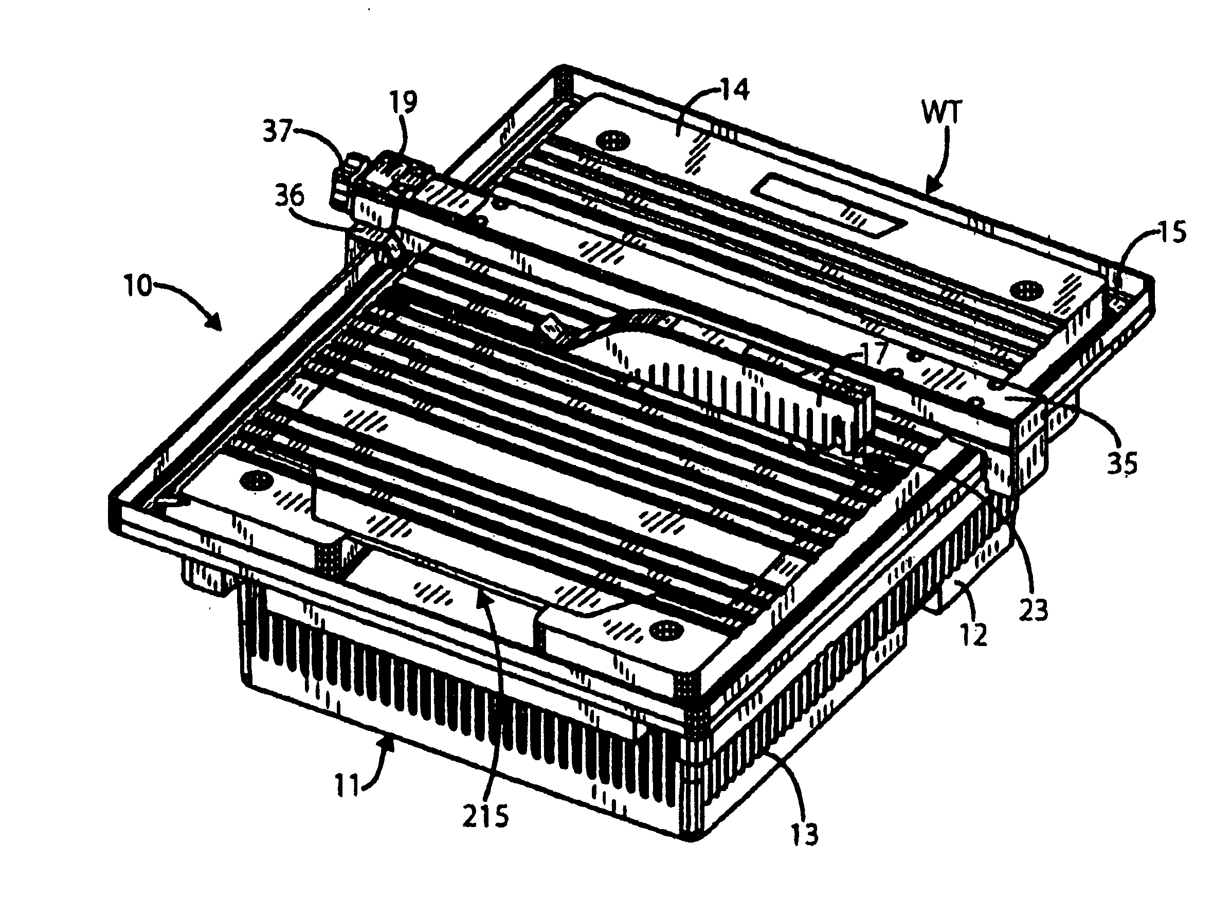
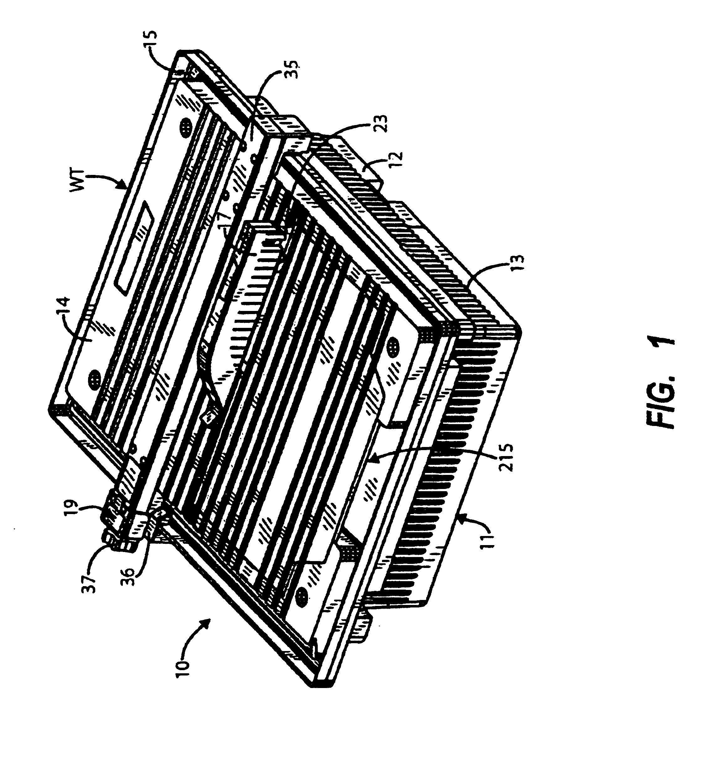
[0045]Referring to FIG. 1 a tile cutter according to an embodiment of the present invention is designated generally by the reference numeral 10. The tile cutter comprises a housing 11 comprising a first compartment 12 for housing a motor (as shown in FIG. 9), and a second compartment 13 for housing the wheel cutter (shown in more detail in FIG. 5). The second compartment 13 also defines an open topped water compartment for holding water which is required during the operation of the tile cutter.

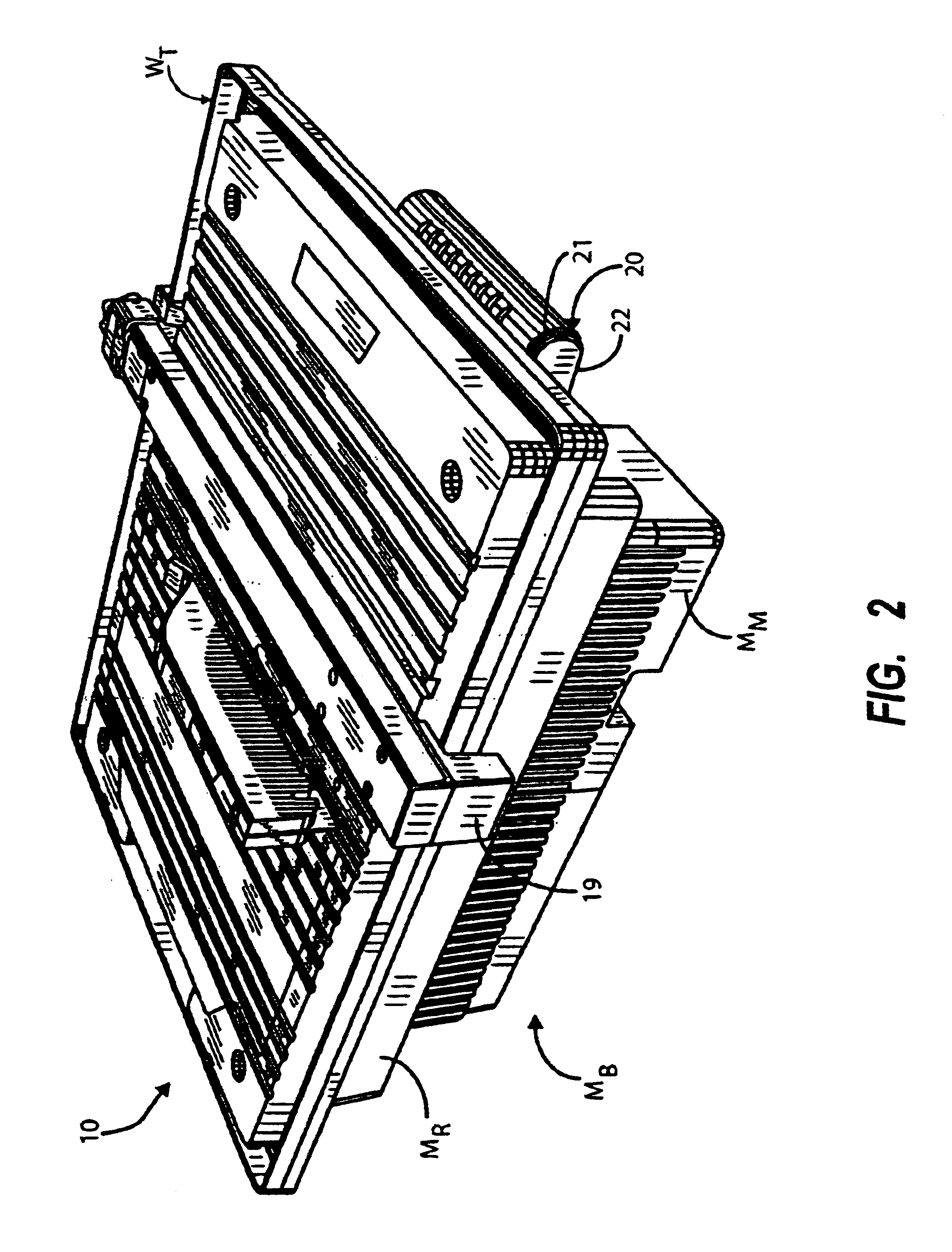
[0046]Referring to FIGS. 4, 5 and 9 it will be seen that the housing 11 includes a main body MB to which a worktop WT is attached; the top WT overlying the entire top of the main body MB. The main body MB is preferably made from two body components, viz. a main body component MR and a minor body component MM. The minor body component MM defines a lower half of the first compartment 12 and the remainder of the main body MB is defined by the main body component MR. FIG. 9 shows the underside of ...


PUM

PropertyMeasurementUnit
Lengthaaaaaaaaaa

Abstract

A tile cutter includes a cutting wheel, a motor which drives the wheel in use, and a main housing body and a worktop mounted on the main housing body to define a cutting surface upon which tiles may be supported when being cut. The main housing body includes a first compartment for housing the motor and a second compartment for housing the cutting wheel. The second compartment defines an open topped water compartment. The worktop has a main body fixedly secured to the main housing body and has an access opening closed by a movable access lid overlying the second compartment to close the open top of the water compartment. The access lid provides access to the water compartment. The worktop further includes one or more open topped drainage channels communicating with the cutting surface and the water compartment to permit, in use, water to drain from the cutting surface to the water compartment.

Description

BACKGROUND OF THE INVENTION[0001]1. Field of the Invention[0002]This invention relates to a tile cutter, and particularly, but not exclusively to a tile cutter for cutting ceramic tiles of the type used to cover walls and floors.[0003]2. Related Art[0004]It is known to cut tiles using a wheel which acts as a cutter in a similar way to a circular saw. The wheel is mounted in a housing on a spindle which allows the wheel to rotate about a substantially horizontal axis. The wheel is driven by a motor. The housing also houses the motor such that the motor is separate from the wheel. This is necessary because during operation of the wheel, water is directed onto the wheel in order to ensure that the tile is cut under wet conditions. Clearly it would be dangerous to allow the motor to come into contact with water.[0005]It is necessary to ensure that the cutting wheel is wet during operation so that fragments of ceramic from the cut tile are removed from the vicinity of the wheel. In addit...

Claims


Application Information

Patent Timeline
IPC IPC(8): B23D47/02B23D47/00B28D7/00B28D7/02B28D1/04B27B27/02B27B27/00B28D1/02
CPCB23D47/025B28D7/02B28D1/04B27B27/02
Inventor BRADFIELD, IAIN
Owner Q E P CO U K
Why Eureka
Try Eureka