Power steering device

a technology of power steering and steering wheel, which is applied in the direction of power steering, fluid steering, vehicle components, etc., can solve the problems of not providing the driver with a satisfied steering feeling, and achieve the effect of reducing or reducing the discomfort of steering and manual steering

Inactive Publication Date: 2005-04-19
HITACHI LTD
View PDF15 Cites 20 Cited by
  • Summary
  • Abstract
  • Description
  • Claims
  • Application Information

AI Technical Summary

Benefits of technology

[0008]An object of the present invention is to provide a power steering device which suppresses or at least minimizes a transmission of pressure pulsation of a hydraulic pump to a power cylinder, thereby providing a driver with a comfortable steering feeling.
[0009]Another object of the present invention is to provide a power steering device which appropriately deals with a residual pressure that would be remained in a power cylinder when a hydraulic pump is off, which provides a driver with a comfortable manual steering feeling.

Problems solved by technology

However, due to inherent constructions, the above-mentioned two power steering devices have failed to provide the driver with a satisfied steering feeling.

Method used


Image

  • Power steering device
  • Power steering device
  • Power steering device

Examples


first embodiment

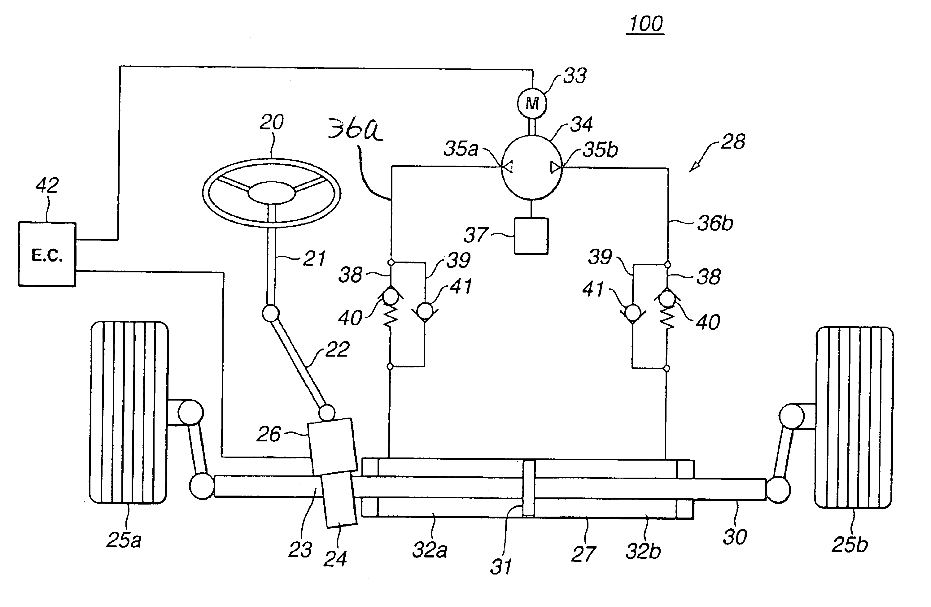
[0023]Referring to FIGS. 1 to 4, particularly FIG. 1, there is schematically shown a power steering device 100 which is the present invention.

[0024]As is seen from FIG. 1, power steering device 100 comprises a steering mechanism including a steering shaft 21 which has a steering wheel 20 connected thereto. An output shaft 22 is connected to steering shaft 21 to rotate therewith. Output shaft 22 has a pinion 24 connected to a lower end thereof. Pinion 24 is meshed with a rack 23 provided at one end of a piston rod 30. A condition sensor 26 is connected to output shaft 22 to detect both a steering torque produced when steering shaft 21 is turned and a bouncing force applied thereto from a road through steered road wheels 25a and 25b. Piston rod 30 has a piston 31 which is slidably received in a power cylinder 27. Due to provision of piston 31, the interior of power cylinder 27 is divided into first and second work chambers 32a and 32b. Thus piston 31 and power cylinder 27 constitute p...

second embodiment

[0043]FIG. 5 shows the pressure characteristics exhibited by a power steering device 200 of the present invention.

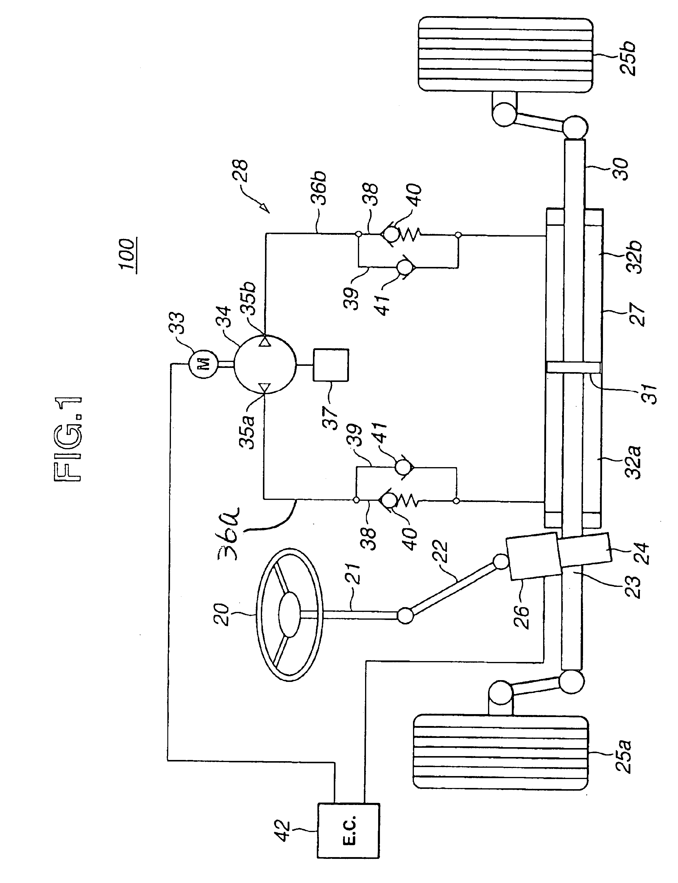
[0044]As shown, in this second embodiment 200, the opening pressure “L” of first valve 40 is set slightly lower than the lowest level “L” of the pulse fluctuation range “Pa” that appears when the hydraulic pressure from pump 34 exhibits its saturated higher level. That is, an allowable fluctuation range “Ps” of the opening pressure “L” of the first valve is set slightly larger than the pulse fluctuation range “Pa” of the pulse pressure from hydraulic pump 34.

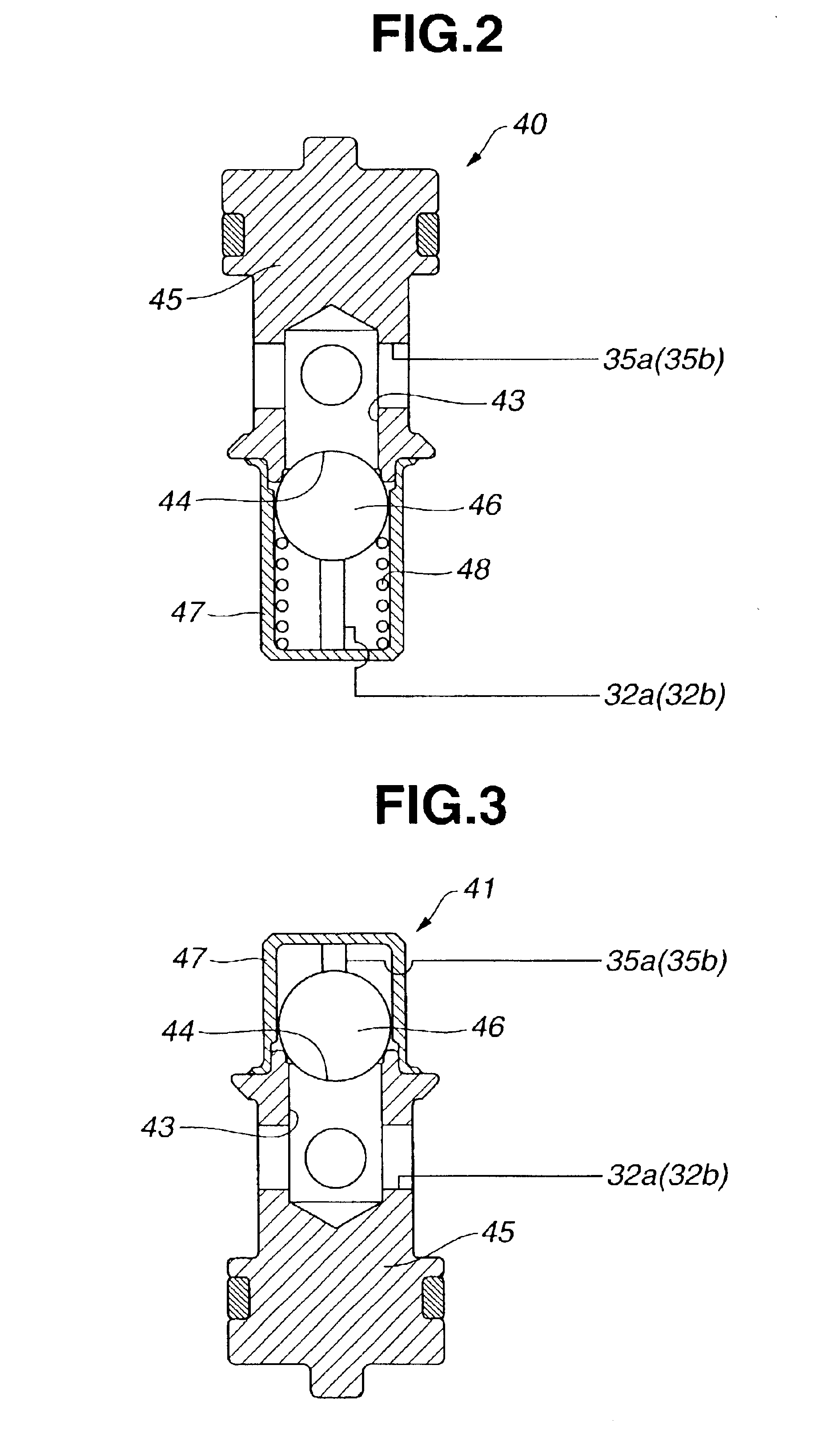
[0045]Accordingly, in this second embodiment 200, the dead zone that induces an inoperative condition of second valve 41 is larger than the pulse fluctuation range “Pa”, and thus, the pressure in work chamber 32a or 32b is not affected by the pulsation from pump 34. Thus, the steering feeling by the driver is much improved.

third embodiment

[0046]Referring to FIG. 6, there is shown a power steering device 300 which is the present invention.

[0047]As shown, power steering device 300 of this third embodiment comprises a steering wheel 20, a steering shaft 21, an output shaft 22, a pinion 24, a rack 23, a condition sensor 26, a power cylinder 27, a piston rod 30 and a piston 31, which are arranged in substantially the same way as that mentioned in the part of first embodiment 100.

[0048]Denoted by numeral 128 is a hydraulic circuit which feeds first and second work chambers 32a and 32b of power cylinder 27 with a controlled hydraulic pressure.

[0049]Hydraulic circuit 128 generally comprises a reversible hydraulic pump 137 which is driven by an electric motor 136, a first fluid passage 134 which connects one outlet / inlet port 137a of pump 137 to first work chamber 32a of power cylinder 27, a second fluid passage 135 which connects the other outlet / inlet port 137b of pump 137 to second work chamber 32b of power cylinder 27, a ...


PUM


Abstract

A first fluid passage extends from a first outlet / inlet port of a hydraulic pump to a first work chamber of a power cylinder, and a second fluid passage extends from a second outlet / inlet port of the pump to a second work chamber of the power cylinder. A switch system switches the role of the first and second outlet / inlet ports in accordance with a turning direction of a steering wheel. Flow control mechanisms are respectively incorporated with the first and second fluid passages, so that a controlled flow of hydraulic fluid from the hydraulic pump to the first or second work chamber and vice versa are appropriately carried out thereby providing the driver with a comfortable steering feeling. A bypass arrangement may be provided between the first and second fluid passages to deal with a residual pressure that would be remained in the first or second work chamber when the hydraulic pump is under inoperative condition.

Description

BACKGROUND OF THE INVENTION[0001]1. Field of the Invention[0002]The present invention relates in general to power steering devices for wheeled motor vehicles, and more particularly to the power steering devices of a type which provides a driver with a comfortable steering feeling.[0003]2. Description of the Related Art[0004]In order to clarify the task of the present invention, two power steering devices hitherto proposed will be briefly described with reference to corresponding drawings.[0005]FIG. 9 shows a power steering device disclosed in Laid-Open Japanese Patent Application (Tokkai-sho) 59-118569. The device of this publication generally comprises a steering shaft 2 having a steering wheel 1 connected thereto. An output shaft 3 is connected to steering shaft 2 through a torsion spring (not shown). Output shaft 3 has a pinion 4b connected to a lower end thereof. Pinion 4b is meshed with a rack 4a provided at one end of a piston rod 5. Piston rod 5 has a piston 10 slidably recei...

Claims


Application Information

Patent Timeline
Patent Type & Authority Patents(United States)
IPC IPC(8): B62D5/06B62D5/065
CPCB62D5/065B62D5/062
Inventor SAKAKI, TOSHIMITSUNAKAZAWA, CHIHARUYOKOTA, TADAHARUKURATA, MASAKAZU
Owner HITACHI LTD
Why Eureka
Try Eureka