Backbone osteosynthesis system with clamping means in particular for anterior fixing

Inactive Publication Date: 2005-04-19
STRYKER EURO OPERATIONS HLDG LLC
View PDF39 Cites 113 Cited by
  • Summary
  • Abstract
  • Description
  • Claims
  • Application Information

AI Technical Summary

Benefits of technology

[0005]An object of the invention is to reduce the number of

Problems solved by technology

Therefore, contact with the patient's body is no lon

Method used


Image

  • Backbone osteosynthesis system with clamping means in particular for anterior fixing
  • Backbone osteosynthesis system with clamping means in particular for anterior fixing
  • Backbone osteosynthesis system with clamping means in particular for anterior fixing

Examples


Embodiment Construction

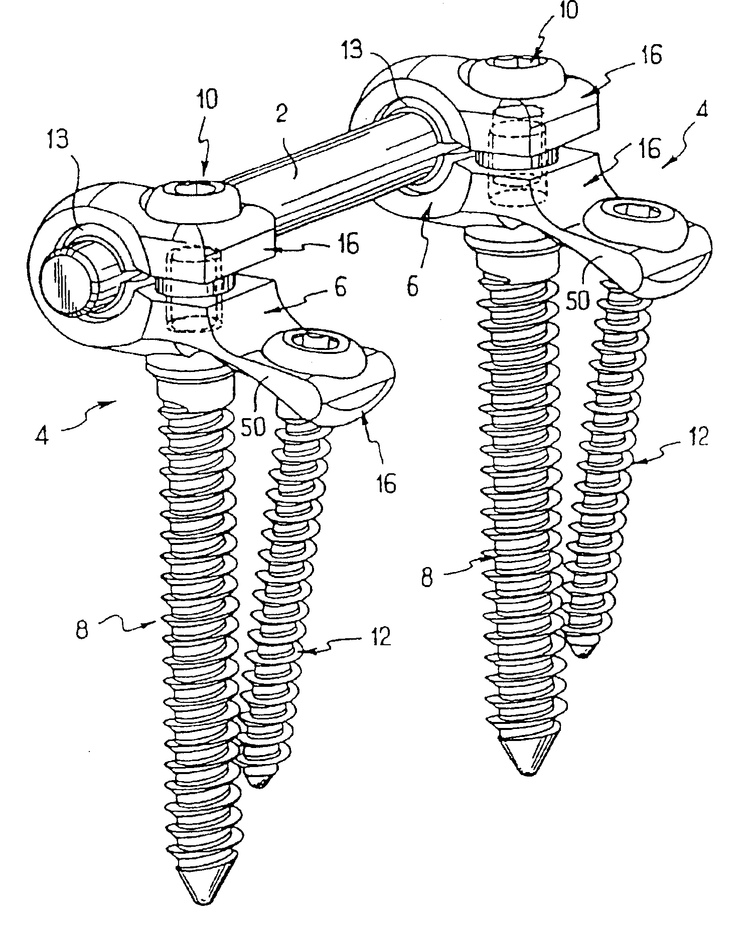
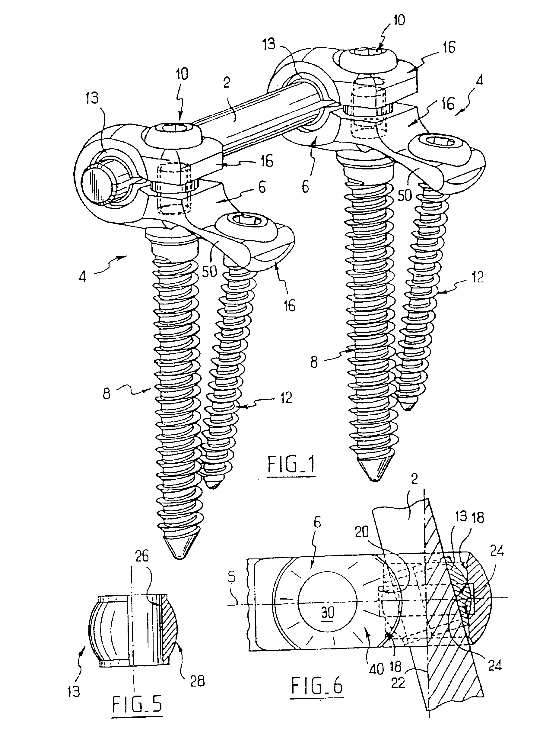
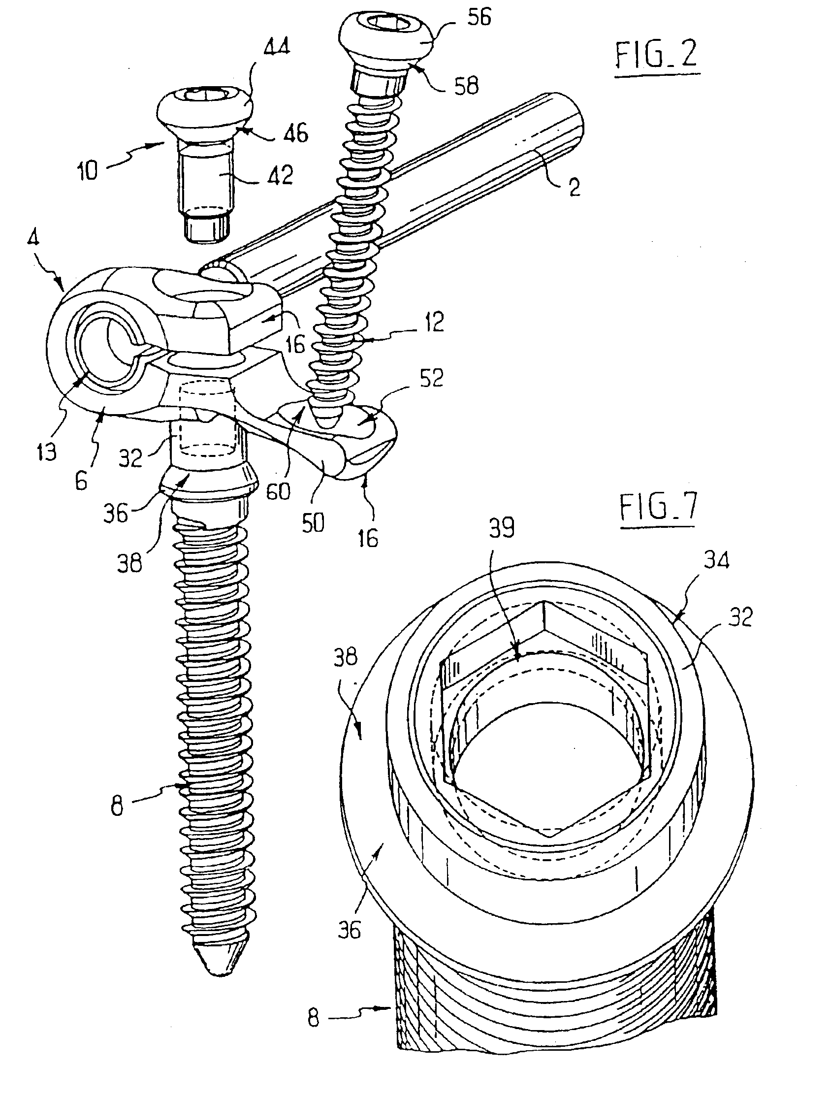
[0039]Referring to FIGS. 1 to 8, the system according to the invention comprises, in the first embodiment, an elongate connection rod 2 of circular cross section and several connector sub-assemblies 4 which can be fixed to the latter. Each of these sub-assemblies, of which two can be seen in FIG. 1 and of which one can be seen in FIG. 2, comprises a connector 6, a first vertebral screw or main screw 8, a clamping screw 10, a second vertebral screw or secondary screw 12, and a ring 13.

[0040]Referring to FIGS. 3 and 4, the connector 6 includes two branches 16 extending opposite to and at a distance from each other, giving the connector a general U-shaped profile. The connector 6 includes a plane of symmetry S perpendicular to the width of the branches 16 and parallel to their length. Referring to FIG. 6 at the point of origin of the branches 16 the connector has two cylindrical and coaxial inner faces 18, 20 with axis 22 perpendicular to the plane S and with different radii, the face ...


PUM


Abstract

The invention concerns a backbone osteosynthesis system, in particular for anterior fixing comprising: an elongated linking element; a vertebral screw with a threaded head; a connector comprising two branches capable of being engaged onto the screw and clamping between them the linking element; and a threaded clamping member capable of co-operating with the head for clamping the branches. The head has a threaded orifice, the clamping member comprising a threaded rod capable of being urged to be engaged in the orifice.

Description

CROSS-REFERENCE TO RELATED APPLICATIONS[0001]This application is a continuation of U.S. application Ser. No. 09 / 674,196 filed Feb. 1, 2001 now U.S. Pat. No. 6,565,569 which is a 371 of PCT 01020 Apr. 29, 1999.BACKGROUND OF THE INVENTION[0002]The invention concerns spinal osteosynthesis systems, in particular for anterior fixation.[0003]The document FR-2,731,344 (U.S. Pat. No. 5,938,663) discloses a spinal osteosynthesis system comprising a rod, a vertebral screw having a body to be anchored in a vertebra, and a head in the form of a threaded rod. The system comprises a connector with two branches which can be engaged on the screw head. A clamping nut can be fitted on the screw head in order to clamp the two branches between the base of the screw head and the nut. The rod engaged between the branches is thus clamped and immobilized.[0004]This system has many advantages. As it includes a small number of components and is easy to put in place, it permits rapid fitting during a surgical...

Claims


Application Information

Patent Timeline
IPC IPC(8): A61B17/70A61B17/58
CPCA61B17/7037A61B17/7044A61B17/7041A61B17/704
Inventor ASSAKER, RICHARDCONCHY, FREDERICLE COUEDIC, REGIS
Owner STRYKER EURO OPERATIONS HLDG LLC
Why Eureka
Try Eureka