Pedal device for a vehicle and automobile using the same

a technology for pedal devices and automobiles, applied in mechanical control devices, foot actuation initiations, instruments, etc., can solve the problems of inability to press the brake pedal with force, and the workload of drivers is large, and achieve the effect of reducing the workload of drivers

Inactive Publication Date: 2005-04-26
HITACHI LTD
View PDF12 Cites 5 Cited by
  • Summary
  • Abstract
  • Description
  • Claims
  • Application Information

AI Technical Summary

Benefits of technology

[0008]An object of the present invention is to provide a pedal device of a vehicle where brake pedal can be strongly depressed when the rapid braking is required and an automobile using the same.
[0011]a footrest means for restricting the turning of the arm member when the driver's force-on-pedal which acts on pedal member is less than the fixed value, and
[0020]According to such configuration, the flexibility can be given to the bending angle of driver's ankle, and the tiredness of the driver can be reduced.
[0034]According to such configuration, the impact on the driver at a moment shifted from the state of footrest to the state of brake operation can be reduced, and the rapid braking which the driver does not intend can be prevented.
[0037]a footrest means for restricting the turning of the arm member when the driver's force-on-pedal which acts on pedal member is less than the fixed value, and
[0039]According to such configuration, the work load to the driver is reduced under the condition that the driver must put the foot on brake pedal for a long time such as the running on the downward slope when jamming, the running by the creep when jamming, and the state of footrest to put the foot on brake pedal while operating the automatic running device.

Problems solved by technology

Therefore, the driver's workload is very large.
Therefore, a first problem is that it is impossible to depress strongly the brake pedal when the rapid braking is required.
Further, there is a second problem in this apparatus.

Method used


Image

  • Pedal device for a vehicle and automobile using the same
  • Pedal device for a vehicle and automobile using the same
  • Pedal device for a vehicle and automobile using the same

Examples


first embodiment

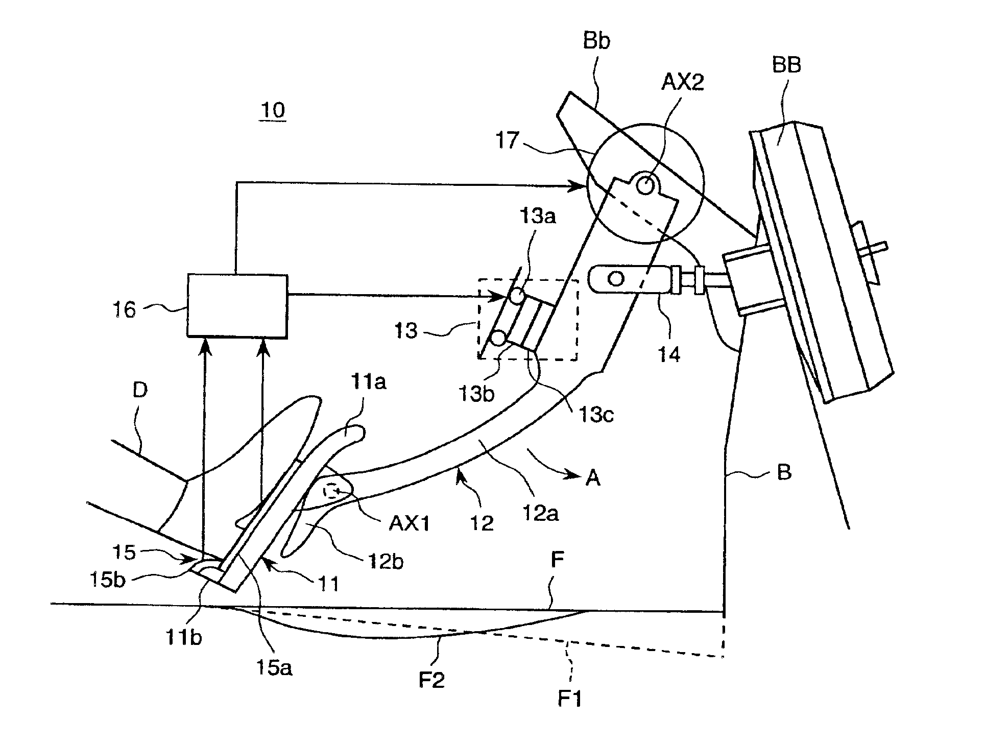
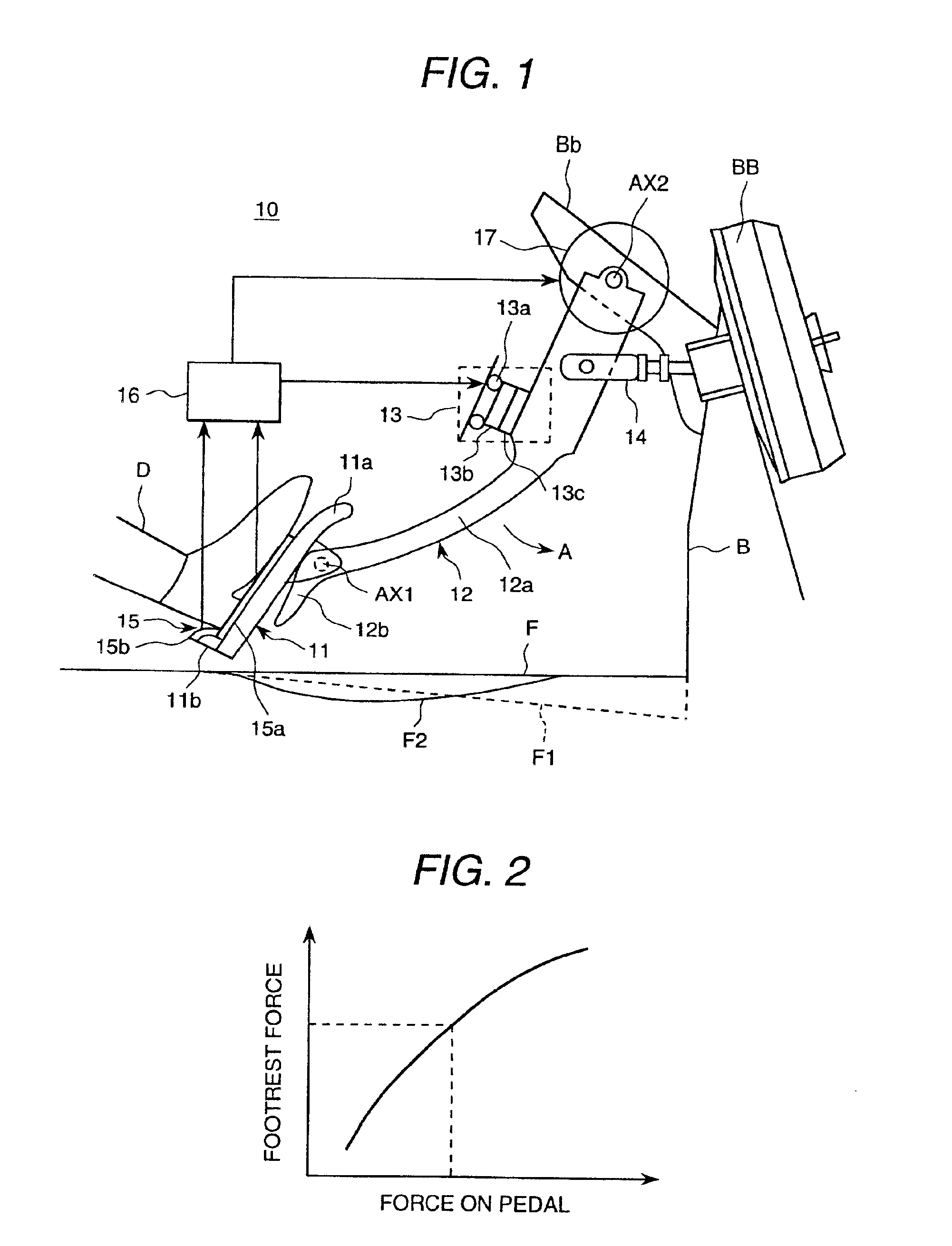
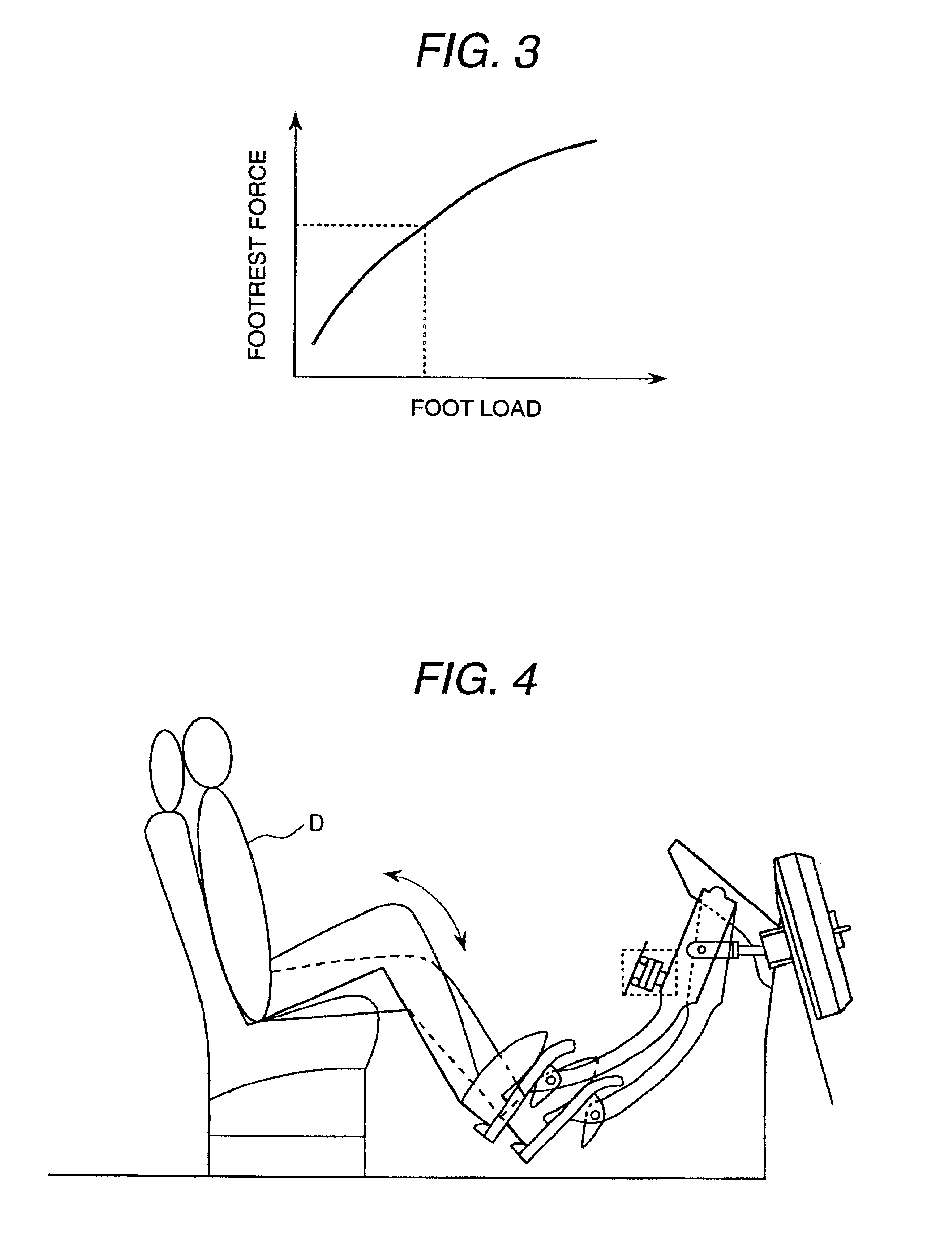
[0064]Here, the footrest function of the pedal device of the vehicle according to this embodiment is explained with reference to FIGS. 2 and 3. These figures are explanatory views of the footrest function of the pedal device of the vehicle according to the present invention.

[0065]Driver D's force-on-pedal and foot load are different in each driver. Then, footrest force calculation means 16 self-adjusts the footrest force by footrest means 13 according to the force-on-pedal and foot load of each driver.

[0066]FIG. 2 shows the relation between the force-on-pedal and the footrest force. As shown, footrest force calculation means 16 increases the amount of the energizing to coil 13a so that the footrest force may increase by increasing of the force-on-pedal.

[0067]Further, FIG. 3 shows the relation between the foot load and the footrest force. Footrest force calculation means 16 increases the amount of the energizing to coil 13a so that the footrest force may increase by increasing of foo...

second embodiment

[0099]Next, the sliding mechanism of the pedal member 11A is explained with reference to FIGS. 8 and 9. FIG. 8 is a plan view showing the configuration of the pedal member used for the pedal device of the vehicle according to the present invention. Further, FIG. 9 is side elevation of FIG. 8. In FIG. 8, the same sign as FIG. 7 shows the same part.

[0100]Slide member 11c is provided with rotatable support wheels 36a and 36b. Further, wheel 35a and 35b are provided in axis AX3. On the other hand, rail member 37, and wheel stoppers 38a, 38b, 38c and 38d are mounted on the floor face.

[0101]Wheels 35a, 35b, 36a and 36b are engaged with rail 37, and they are rotatable on rail 37. As a result, slide member 11c can slide to the floor face.

[0102]Next, another sliding mechanism of the pedal member 11A is explained with reference to FIG. 10.

[0103]FIG. 10 is a side elevation showing another configuration of the pedal member used for the pedal device of the vehicle according to the second embodim...

third embodiment

[0112]Next, the configuration of the pedal device of the vehicle according to the present invention and its operation are explained with reference to FIGS. 11-13. The configuration of the pedal device of the vehicle according to this embodiment is similar to one shown in FIG. 7. First, the sliding mechanism of the pedal member 11A is explained with reference to FIGS. 11 and 12.

[0113]FIG. 11 is a side elevation showing the configuration of the pedal member used for the pedal device of the vehicle according to the third embodiment of the present invention. FIG. 12 is a plan view of the configuration shown in FIG. 11. In FIGS. 11 and 12, the same sign as FIGS. 7 and 8 designates the same part.

[0114]Roller support members 40a, 40b, 40c and 40c to support rollers 39a, 39b, and belt member 41 are provided on the floor face. Slide member 11c is fixed to a part of belt member 41. Slide member 11c smoothly moves on the floor face because belt member 41 operates with the movement of slide mem...


PUM


Abstract

Pedal device 10 has a pedal member 11 depressed by the driver, and arm member 12 engaged with the pedal member, for turning when the pedal member is depressed, and transmitting driver's force-on-pedal to the brake master cylinder. When the driver's force-on-pedal which acts on pedal member 11 is less than the fixed value, footrest means 13 restricts the turning of the arm member. Pedal member 11 is composed of footplate 11a to be depressed by the driver, and protruding portion 11b engaged with the footplate, on which driver's heel can be put.

Description

BACKGROUND OF THE INVENTION[0001]The present invention relates to a pedal device for a vehicle and an automobile using the same, particularly to a pedal device of a vehicle suitable for the use in the vehicle having an automatic cruise control where the driver does not need the accelerator operation and an automobile using the same.[0002]Recently, a self-control system is being developed, in which the speed of automobile can be controlled to become a preset speed of automobile, for example, like following distance control automatic cruise (ACC: Adaptive Cruise Control), and an engine, a motor, a transmission, and a brake is self-controlled so as to keep the safe following distance by detecting the distance between this car and the preceding car with radar. In this case, only the start and acceleration are controlled automatically and the stop and deceleration are controlled based on driver's will to improve safety more. As the method for that, the deceleration and the stop are contr...

Claims


Application Information

Patent Timeline
Patent Type & Authority Patents(United States)
IPC IPC(8): B60T7/06B60T7/04G05G1/42G05G1/487G05G1/60G05G5/03
CPCB60T7/06G05G1/30G05G1/42G05G1/487G05G5/03G05G1/60Y10T74/20918Y10T74/20528Y10T74/20888Y10T74/2054
Inventor KOJIMA, TAKAOMINOWA, TOSHIMICHIKURAGAKI, SATORUSATOU, KAZUHIKOYOSHIKAWA, TOKUJI
Owner HITACHI LTD
Why Eureka
Try Eureka