Passive valve assembly

a valve assembly and valve body technology, applied in the direction of valve operating means/release devices, non-mechanical valves, machines/engines, etc., can solve the problems of small parasitic losses and inability to operate, and achieve the effect of valve opening tim

Inactive Publication Date: 2005-04-26
INNOGY
View PDF8 Cites 88 Cited by
  • Summary
  • Abstract
  • Description
  • Claims
  • Application Information

AI Technical Summary

Benefits of technology

[0027]With this arrangement the valve can be opened while the pressure in the first cylinder is less than the pressure on the other side of the valve head. This is important in applications where the open time of the valve is very short. Although it will result in a small amount of reverse flow around the valve head, this will be insignificant, and will be more than compensated for by the advantages obtained from opening the valve at the correct time.
[0028]The biasing force may be provided by any well known means, for example a resilient member such as a mechanical spring. However, preferably, the valve element is provided with a piston, and the biasing force is provided by pressurised gas acting on at least one side of the piston. This arrangement using pressurised gas is better suited to the pressures associated with a valve of a reciprocating compressor, and also allows ready adjustment of the operating point of the valve by varying the pressure of the gas.

Problems solved by technology

As almost all of the energy used to compress the gas in the first chamber when the valve moves away from its seat is recovered when the valve reverses its direction, parasitic losses are small.
Also, the closing point of the valve can be controlled by the engine control system, which is not possible using plate valve.

Method used


Image

  • Passive valve assembly
  • Passive valve assembly
  • Passive valve assembly

Examples


Embodiment Construction

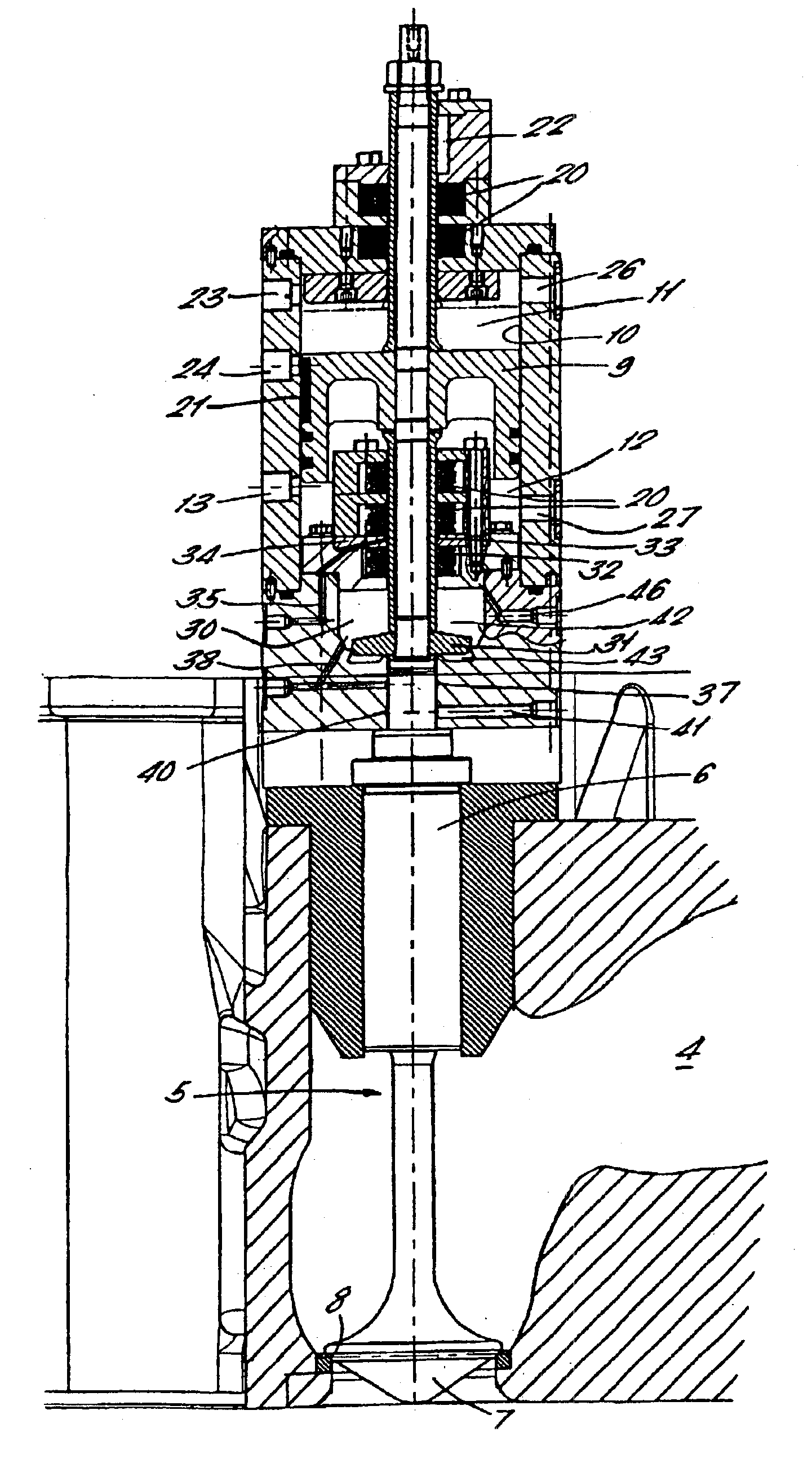
[0035]The valve to be illustrated and described is particularly applicable as the discharge valve for a reciprocating compressor such as that disclosed in WO 94 / 12785.

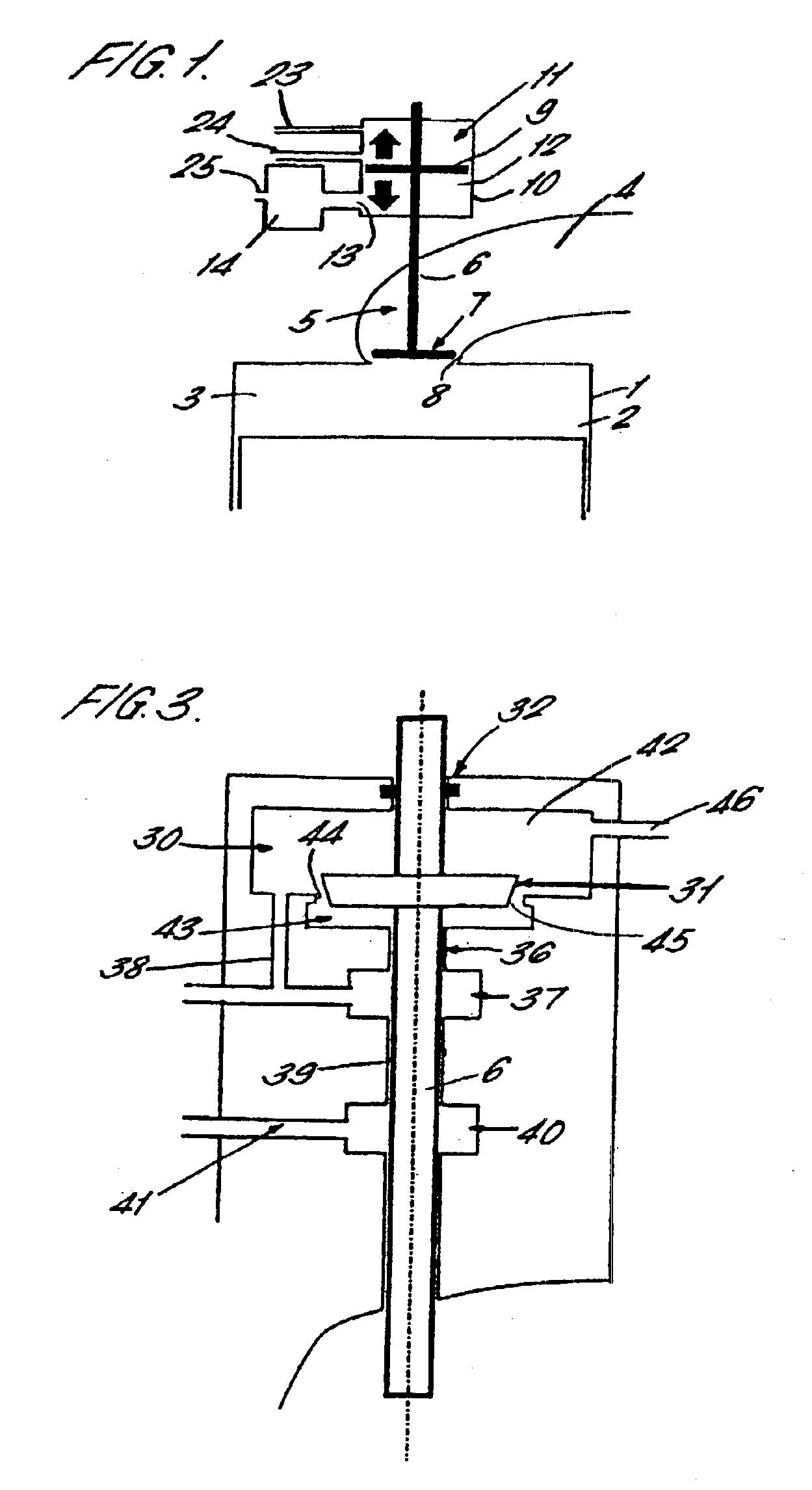
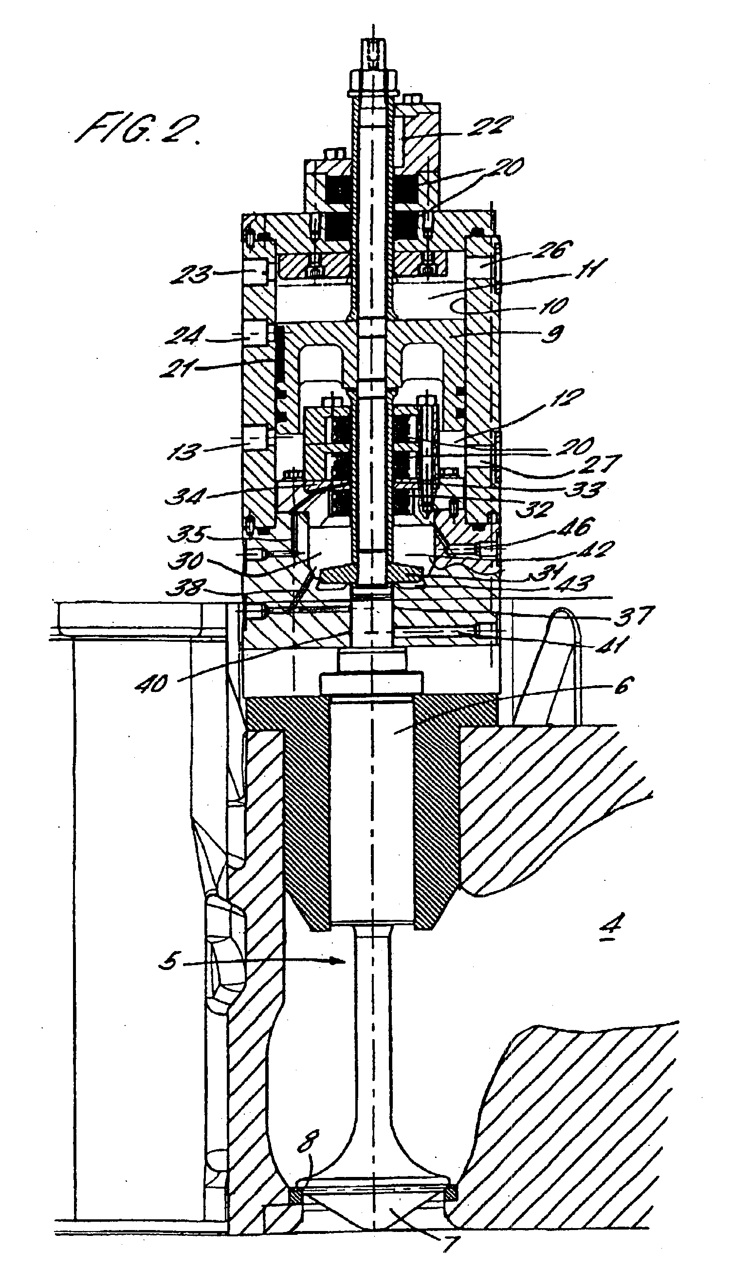
[0036]The reciprocating compressor comprises a first cylinder 1 in which a member 2 is reciprocable to compress gas in a compression chamber 3 above the reciprocating member 2. Gas to be compressed enters the compression chamber 3 through an inlet port (not shown) controlled by an inlet valve (not shown) and the compressed gas leaves the chamber through discharge port 4 controlled by discharge valve element 5 which opens away from the compressor chamber 3, namely upwardly as shown in FIGS. 1 and 2.

[0037]The discharge valve element 5 is a poppet valve comprising a valve stem 6 having a head 7 at one end which seats in a seat 8 in the first cylinder 1. At the opposite end of the valve stem 6 to the head 7 is a piston 9 which is reciprocably movable within a cylinder 10. The piston 9 divides the cylinder 10 into a first c...


PUM


Abstract

A passive valve assembly for controlling the flow into or out of chamber (3) through a port (4). The valve assembly comprises a valve element (5) arranged to open in the direction of flow through the port. The valve element (5) has a piston (9) which is reciprocable in a cylinder (10) containing gas. On opening of the valve, gas is compressed in a first chamber (11) of the cylinder (10), and this energy of compression is used to reverse the direction of the valve element (5) and return it to its seat.

Description

[0001]This application is the national phase under 35 U.S.C. § 371 of PCT International Application No. PCT / GB01 / 01443 Which has an International filing date of Mar. 30, 2001, which designated the United States of America.FIELD OF THE INVENTION[0002]The present invention relates to a passive valve assembly for controlling flow into or out of a first cylinder in which a member, such as a piston, is reciprocable. Such a cylinder may be, for example, part of an internal combustion engine or a reciprocating air compressor.BACKGROUND OF THE INVENTION[0003]Valves for such applications can be broadly divided into two categories, namely active and passive. Active valves have an external means of actuation, while passive valves are activated only by pressure changes occurring during normal operation of the system.[0004]Conventional diesel engines use active valve assemblies in which, typically, a cam and spring arrangement open and close poppet valves. This is a simple mechanical device whic...

Claims


Application Information

Patent Timeline
Patent Type & Authority Patents(United States)
IPC IPC(8): F01L1/00F01L3/20F01L3/00F01L1/46F01L9/02F01L9/00F01L9/10F16K31/122
CPCF01L1/46F01L9/02F01L3/20F01L2003/258F01L9/10
Inventor CONEY, MICHAEL WILLBOUGHBY ESSEXMALE, ANDREWWEST, DAVID FRANKLANDPORTER, BRIAN CHARLESSPELLIERS, LAURENT ROGER
Owner INNOGY
Why Eureka
Try Eureka