Combinative decorative light equipment

a technology of decorative lamps and light fixtures, applied in the direction of lighting and heating apparatus, lighting support devices, color-music devices, etc., can solve the problems of increasing costs and difficult installation of decorative lamps on top of decoration frameworks, and achieve the effect of increasing the variation of appearance and enhancing the bliss of celebration

Inactive Publication Date: 2005-04-26
CHEN JOHNNY
View PDF4 Cites 91 Cited by
  • Summary
  • Abstract
  • Description
  • Claims
  • Application Information

AI Technical Summary

Benefits of technology

[0005]Accordingly, the present invention has been made to solve the aforesaid problem occuring in the prior art, and an object of the present invention is to provide a combinative decorative light equipment which has a plurality of lamp groups connected to each other with connectors, and is hung on the individual frameworks having connecting devices and controlled by a controller individually so as to achieve a dynamic sensitized decorative effect.
[0006]Another object of the present invention is to provide a combinative decorative light equipment wherein a plurality of lighting element connected by wires in series or series-parallel manner into several lamp groups of the same function so as to express the effect of glittering or constant lighting and enhance the bliss of celebration, this is the other object of the present invention.
[0007]According to the combinative decorative light equipment of the present invention, the structural framework call be in the tree shape, planer or three-dimensional to increase the variation of the appearance. This is another object of the present invention.

Problems solved by technology

In early days, pre-assembled decoration frameworks were mostly used, with decorative lamps encircling the decoration frameworks so that it is not easy for the decorative lamps to be installed on top of the decoration frameworks.
Moreover, it is not convenient to recycle the decorative lamps around the decoration frameworks when they are dissembled, thereby increasing the cost.

Method used


Image

  • Combinative decorative light equipment
  • Combinative decorative light equipment
  • Combinative decorative light equipment

Examples


Embodiment Construction

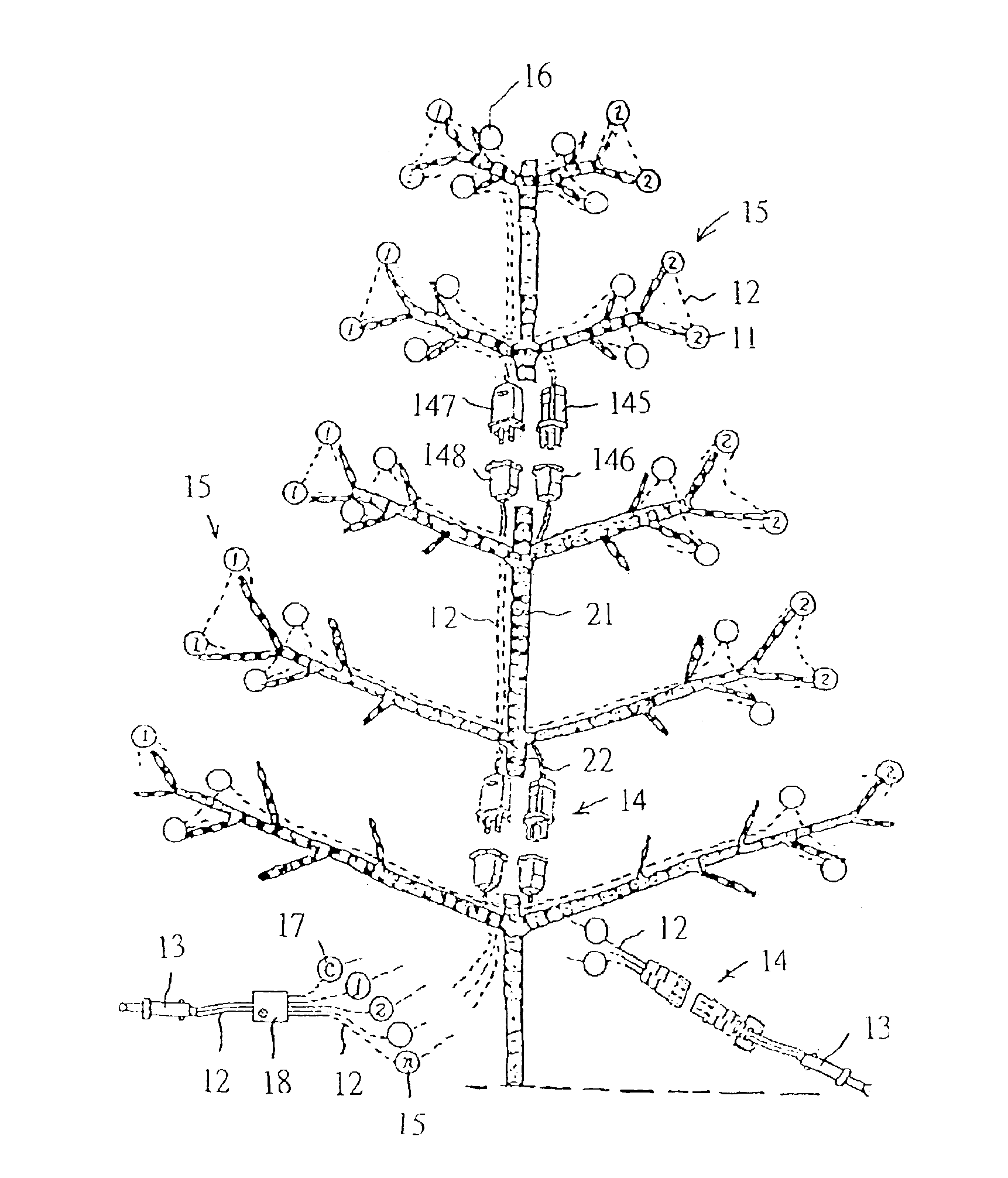
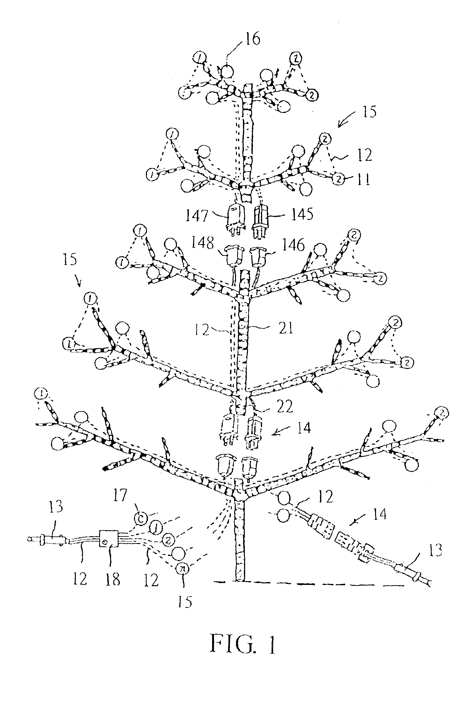
[0012]As shown in FIG. 1, the combinative decorative lighting equipment of the present invention comprises a structural framework 21 and at least a lamp series 2, the framework 21 is configurated in a tree shape on which connectors 22 are installed with several wires 12 which are jointly connected to a functional controller 18. Then, the functional controller 18 is connected to a power supply connector 13 (such as a connector or a plug). The mentioned lamp series 2 is formed with a plurality of lighting elements 11 installed on suitable positions of the structural framework 21. Each of the lighting elements 11 formed of LEDs or tungsten lamps is mutually connected by wires 12 in series or series-parallel manner, and respectively connected into lamp groups 15, 16 of different appearance in different positions. Said lamp groups are respectively connected upwardly and downwardly to the functional controller 18. And Each circuits 17 is come out from the functional controller 18 respecti...


PUM


Abstract

Disclosed is a combinative decorative light equipment wherein a plurality of lighting elements are mutually connected into several individual lamp groups by wires in series or series-parallel manner, so as to be hung on a structural framework. The upper connectors of said lamp groups are installed on the connecting device of different structural frameworks, and which are connected into a decoration framework, so that the lamp groups on different structural frameworks are mutually connected to form larger lamp groups and assembled into a pre-designed decoration body.

Description

BACKGROUND OF THE INVENTION[0001]1. Field of the Invention[0002]The present invention relates to a combinative decorative light equipment, and more particularly to a combinative decorative light equipment with lamp groups hung on individual structural frameworks. The connectors of lamp groups are installed on the connecting device of individual structural frameworks, so that the lamp groups are mutually connected to form larger lamp groups after a plurality of frameworks are assembled into a decoration framework.[0003]2. Description of the Prior Art[0004]Starry lamp series are frequently decorative articles in festival occasions, commercial advertisement, and special occasions for the effect of glittering like stars. A suitable amount of lamps is required for the lamp series to prevent them from being burned due to overloading, and to decorate with a decoration framework (e.g. artificial trees) so as to express the happy atmosphere of festivals fully. In early days, pre-assembled de...

Claims


Application Information

Patent Timeline
Patent Type & Authority Patents(United States)
IPC IPC(8): A47G33/00A47G33/06F21V23/06F21S4/00F21V23/00
CPCA47G33/06F21S4/001F21V23/06Y10S362/806F21W2121/04F21Y2101/02F21S4/10F21Y2115/10
Inventor WU, JENG-SHYONG
Owner CHEN JOHNNY
Why Eureka
Try Eureka