Scope adjustment method and apparatus

a technology of optical sighting and adjustment method, which is applied in the direction of manufacturing tools, portable drilling machines, instruments, etc., can solve the problems of increased difficulty in sighting in firearms, potential errors in firearm sighting, and subsequent shots at targets at non-zero distances

Inactive Publication Date: 2005-05-03
BELL JOHN CURTIS +1
View PDF56 Cites 187 Cited by
  • Summary
  • Abstract
  • Description
  • Claims
  • Application Information

AI Technical Summary

Benefits of technology

[0018]In one embodiment, he detector comprises a rangefinder that determines a range to the target at a location indicated by the point of aim. The range allows an elevation adjustment of the point of aim. In one embodiment, the detector comprises a wind velocity detector that determines a wind velocity so as to facilitate windage adjustment of the point of aim. In one embodiment, the detector comprises an inclinometer adapted to determine the firearm's shooting angle with respect to a horizontal line so as to facilitate correction to an elevation adjustment of the point of aim that is based on substantially horizontal shooting.
[0028]In one embodiment, the detector comprises a rangefinder that determines a range to the target at a location indicated by the point of aim. The range allows an elevation adjustment of the point of aim. In one embodiment, the detector comprises a wind velocity detector that determines a wind velocity so as to facilitate windage adjustment of the point of aim. In one embodiment, the detector comprises an inclinometer adapted to determine the firearm's shooting angle with respect to a horizontal line so as to facilitate correction to an elevation adjustment of the point of aim that is based on substantially horizontal shooting.
[0033]Yet another aspect of the present teachings relates to a method of adjusting a point of aim of an optical sight for a firearm. The method comprises shooting a first bullet towards a first point of aim, and visually observing the first bullet's point impact relative to the first point of aim. The method further comprises adjusting the first point of aim to a second point of aim without having to remove sight of the sight picture through the optical sight such that the second point of aim is closer to the point of impact.
[0034]In one implementation, the method further comprises shooting a second bullet towards the second point of aim to confirm the adjustment. Adjusting the point of aim comprises manipulating a remote controller that induces the point of aim to be moved without the shooter having to touch a point of aim movement mechanism.
[0035]Yet another aspect of the present teachings relates to a scope system for a rifle. The system comprises a movement mechanism coupled to an existing reticle adjustment assembly. The movement mechanism includes a powered driver that causes the reticle to move with respect to an optical axis of the scope. The system further comprises a remote controller that outputs a signal to the movement mechanism thereby causing the powered driver to move the reticle. The remote controller outputs the signal in response to a shooter's manipulation of the remote controller disposed proximate the rifle so as to allow the shooter to manipulate the remote controller without having to lose the sight picture.

Problems solved by technology

Each manipulation of the scope adjustment usually requires the shooter to disturb the scope sight picture.
Furthermore, subsequent shots at targets at non-zeroed distances may be subject to shooter's estimate errors.
The continuous repetition of this process results in potential errors in the sighting in of the firearm.
Flinching can then result in the shooter introducing error into the shooting process thereby increasing the difficulty in sighting in the firearm.
A further difficulty with firearms is that the shooter must often have to estimate the deviation between the point of aim and the point of impact due to distance.
Naturally, estimating the range can be very difficult, particularly when it must be done very quickly as is common in hunting or combat situations.

Method used


Image

  • Scope adjustment method and apparatus
  • Scope adjustment method and apparatus
  • Scope adjustment method and apparatus

Examples


embodiment 174

[0083]In the embodiment 174 of the adjustment mechanism, the motor 210 is powered by a battery. The motor 210 rotates in response to a motor signal from a control unit 216 that results from a signal from the remote controller (not shown). A housing 214 houses the battery 212, motor 210, control unit 216, and the driver member 200.

[0084]It should be apparent that the motor 210 and the battery 212 can be selected from a wide variety of possible types, depending on the performance criteria. It will be appreciated that the motor 210 may be powered by a power source other than a battery without departing from the spirit of the present teachings. For example, the adjustment mechanism may be adapted to be powered by an external source, such as a battery adapter.

[0085]It will also be appreciated that the adjustment mechanism may be adapted to couple to numerous other types of scopes. For example, some scopes may have knobs (instead of slots) for turning the threaded actuators therein. In su...

embodiment 224

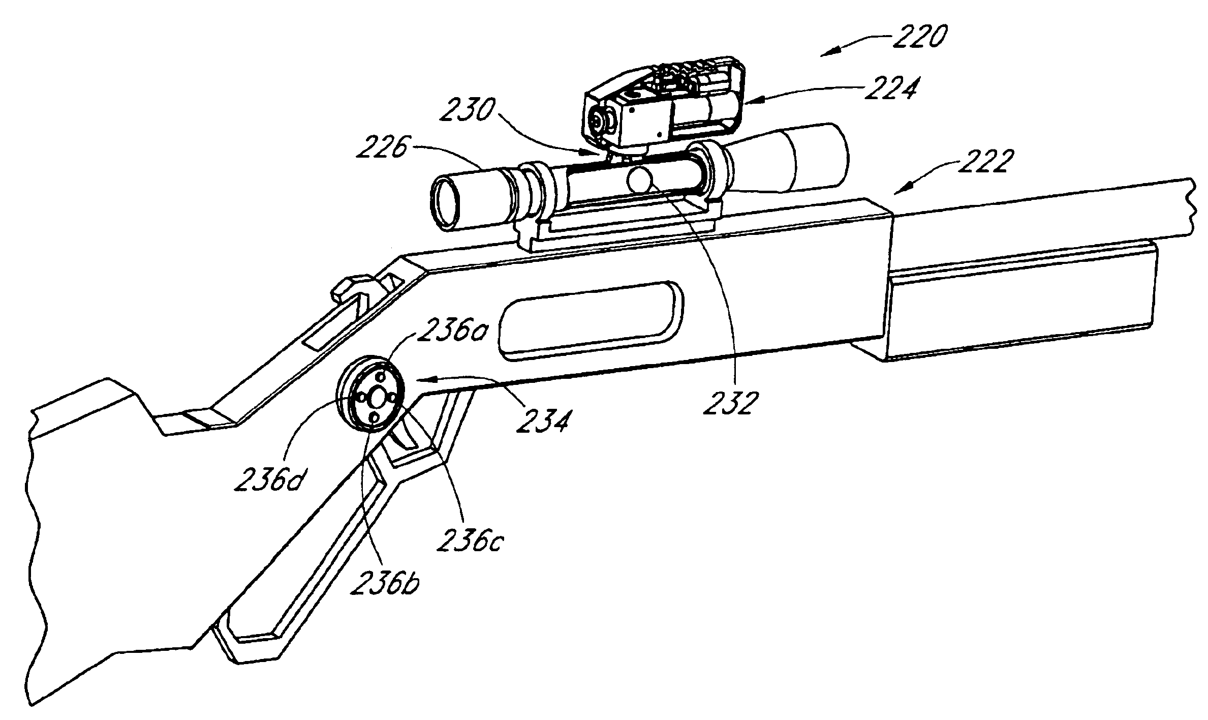
[0092]In FIG. 7, the adjustment mechanism 224 is shown to be coupled via the coupling 230. The internal components within the transfer mechanism 242 and the coupling 230 are described below in greater detail. The transfer of the X-motion to the Y-motion allows moving of a adjustment tube 240 with respect to the scope tube 226 in a manner described below. In the embodiment 224 shown in FIG. 7, the battery 250, motor 252, and the transfer mechanism housing are enclosed within an outer housing 256.

[0093]FIG. 8 now illustrates a partially disassembled view of the transfer mechanism 242. The mechanism 242 comprises a housing 262 having an input portion 264 and an output portion 266. The input portion 264 is adapted to receive a bolt 270. In one embodiment, the bolt 270 comprises a elongate member having a threaded portion 272, an engagement surface 274, and a smooth portion 276 therebetween. The threaded portion 272 is adapted to engage its counterpart threads (shown in FIGS. 9 and 10) w...


PUM


Abstract

A rifle scope system allows adjustment of the scope while a shooter maintains the shooting posture and the scope sight picture. The scope system comprises an adjustment system comprising an electromechanical mechanism that responds to a signal from a remote controller manipulated by the shooter without having to significantly disturb the shooting posture. The adjustment system allows the shooter to adjust the scope's point of aim to coincide with a bullet's point of impact at a target. Such adjustment can be performed either by the shooter. Alternatively, such adjustment could be performed by a processor configured to adjust the point of aim based on a ballistic parameter associated with the bullet or the shooting environment. The adjustment system allows such processor-determined adjustments to be effected in a quick manner.

Description

RELATED APPLICATIONS[0001]This application claims priority from U.S. provisional application Ser. No. 60 / 381,922, filed on May 18, 2002.BACKGROUND[0002]1. Field[0003]The present teachings generally relate to systems and methods for optical sighting of firearms and, in various embodiments, to a system and method for adjusting a point of aim of a rifle scope without having to significantly disturb the shooter's scope sight picture and the shooting posture.[0004]2. Description of the Related Art[0005]Many firearms such as rifles are equipped with optical scopes to aid in accurate positioning of the firearm's point of aim (POA). When shot, a bullet's point of impact (POI) at a target varies depending on various ballistic parameters associated with the bullet and the shooting environment. Some of the common ballistic parameters include, for example, the bullet type, distance to the target, and wind speed.[0006]In order to place the bullet where the rifle is aimed at, the POA needs to coi...

Claims


Application Information

Patent Timeline
Patent Type & Authority Patents(United States)
IPC IPC(8): F41G1/387F41G1/00F41G1/54F41G11/00
CPCF41G11/001F41G1/54
Inventor BELL, JOHN CURTISSEIDEL, KENDALL
Owner BELL JOHN CURTIS
Why Eureka
Try Eureka