Composite tension rod terminal systems

a technology of tension rod terminal system and composite fiber, which is applied in the direction of marine propulsion, special-purpose vessels, vessel construction, etc., can solve the problems of unable to provide a terminal system that is commercially successful, the potential advantages of composite tension rods are largely defeated, and the use of composite tension rods has languished, so as to achieve the effect of superior combination of strength and lightness

Inactive Publication Date: 2005-05-03
THOMAS GEORG K
View PDF26 Cites 55 Cited by
  • Summary
  • Abstract
  • Description
  • Claims
  • Application Information

AI Technical Summary

Benefits of technology

[0009]These and related features, more fully described below, result in light and geometrically slim terminal arrangements which may be used at the ends of tension rods employed in the rigging of a yacht to provide a superior combination of strength and lightness in both tension rods and fittings at many or all points, high and low, throughout the rigging.

Problems solved by technology

If heavy and bulky fittings are required for each end of each stay, cable or rod, the potential advantages of the composite tension rods are largely defeated.
Composite tension rods reinforced with carbon fibers or other of the fiber materials mentioned above are believed to have been pultruded as rods of circular cross-section and tried in performance applications as diagonals and verticals in yacht rigging, but so far as known, to date no commercially successful design of terminal system has been provided for such rods, and their use has languished.
This means when the rigging is slack (low tension) the fitting and rods will bend relative to one another, and wear and fatigue at the entrance to the terminal fitting will result in premature failure.

Method used


Image

  • Composite tension rod terminal systems
  • Composite tension rod terminal systems
  • Composite tension rod terminal systems

Examples


Embodiment Construction

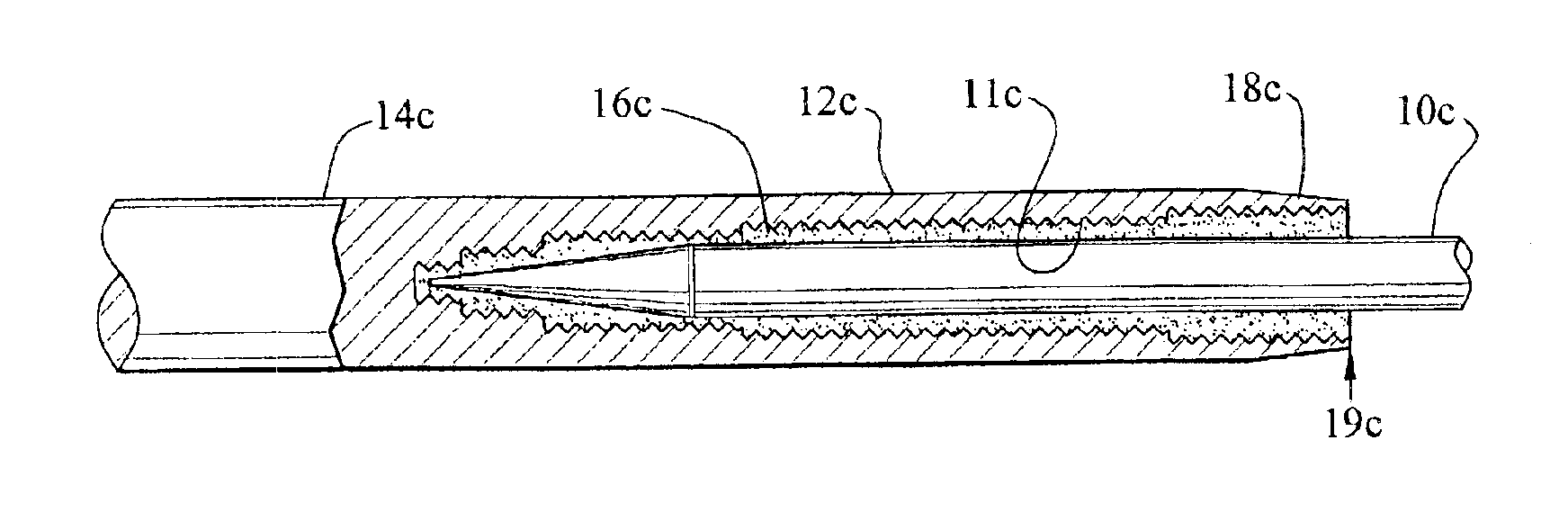
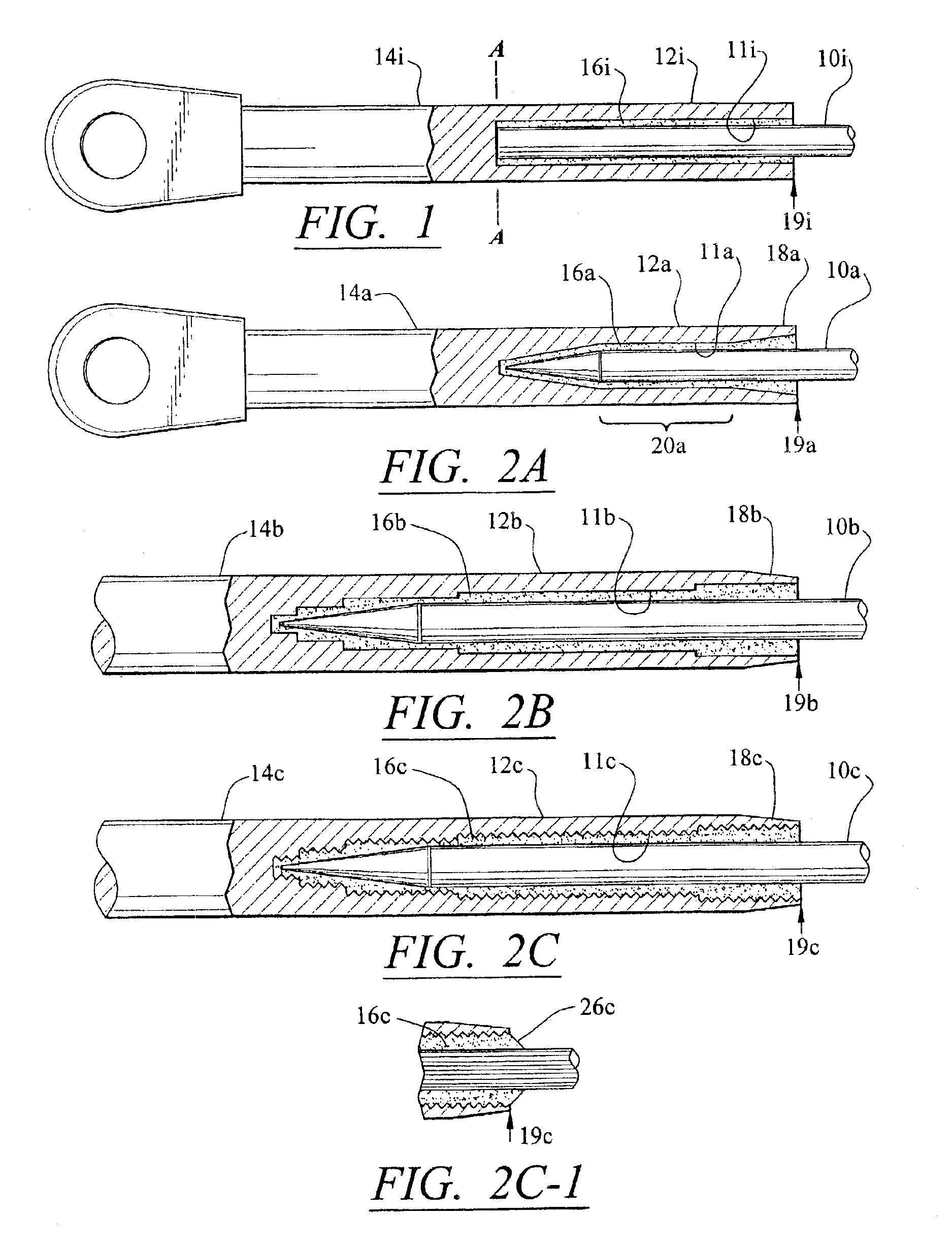
[0029]In order to best describe the terminal systems of the invention, it is convenient to first describe an imaginary or hypothetical terminal system. Imagine a terminal system at one end of a composite tension rod as seen in FIG. 1. The tension rod, labeled 10i in the drawing, is of conventional round (circular) cross-section, and is received in the bore 11i of a sleeve 12i. The sleeve is formed as part of the shank 14i of a terminal fitting, in this case an eye. The eye may have a threaded bore (not shown) in which exterior threading (not shown) on the shank is received, the eye being turned down tightly on the shank to form a fitting, in this case the eye. The shank could join to parts other than an eye to form other common types of fittings, such as forks, stud terminals, or swivel bails, or join to tees, cross-pins or barrels that form part of toggle connections, or the shank could be somewhat elongated and threaded for a required adjusting distance to function as part of a tu...


PUM

PropertyMeasurementUnit
diameteraaaaaaaaaa
lengthsaaaaaaaaaa
lengthsaaaaaaaaaa

Abstract

A composite tension rod is received in the sleeve portion of a shank that forms part of a terminal fitting, and is spaced from the shank sleeve and connected thereto by a potting resin. The shank sleeve wall tapers out from thin at its distal end to thick at the bury depth of the rod. The rod is tapered outwardly from a point of minimum diameter at its inner end to its full diameter a given distance from the end. The shank sleeve and rod have complementary dual tapering along said length such that as the diameter of the rod along said distance increases, the wall thickness of the shank sleeve decreases. The resin layer and the rod are secured to each other against relative longitudinal movement, as are the resin layer and the shank sleeve.
In another aspect of the invention, a tension rod sleeve is fixed to the tension rod and extends over the distal end of the shank sleeve and along all or a majority of the length of the shank sleeve. The rod sleeve is tapered so that its wall thickness decreases to a minimum in the vicinity of the proximal end of the shank sleeve, or the rod sleeve, as it extends along the shank sleeve, is divided, or divides, into two halves or bands which join to form loop extending around a loop-engaging, convex, fiber-turnaround face formed on the terminal fitting. Such face extends transversely from one side to the other of the fitting.

Description

FIELD OF THE INVENTION[0001]This invention relates to terminal systems for composite fiber-reinforced resin tension rods, or cables made up of multiple rods, generally formed by pultrusion, hereinafter collectively referred to as fiber-reinforced composite rods, fiber-reinforced rods, composite tension rods, or as composite rods, or tension rods, or simply rods, and comprising carbon-fiber-reinforced resins, or resins reinforced with other fibers, and having the properties of geometric slimness and high tensile strength per unit weight. “Other fibers” includes fibers such as Kevlar®, Spectra®, Zylon®, and Twaron® brands of fiber, and, in general, fibers or blends of fibers that provide high tensile strength per unit weight when combined with a polymer resin matrix.[0002]Composite tension rods differ from ropes or lines made of strands of twisted fibers consisting of fiber materials that are the same or similar to the fiber materials just mentioned. Unlike ropes or lines made of stra...

Claims


Application Information

Patent Timeline
Patent Type & Authority Patents(United States)
IPC IPC(8): B63H9/08B63H9/00E04C5/07F16C7/00F16C7/02
CPCB63H9/08E04C5/07E04C5/085F16C7/02E04C5/127Y10T403/635Y10T403/471Y10T403/473F16C2326/30
Inventor THOMAS, GEORG K.
Owner THOMAS GEORG K
Why Eureka
Try Eureka