Shaft sealing assembly

a technology for sealing parts and shafts, applied in the direction of engine seals, mechanical equipment, engine components, etc., can solve the problems of reducing the flexibility reducing the effectiveness of the lip seal, and abnormal wear of the lip portion, so as to improve the durability of the lip portion

Inactive Publication Date: 2005-05-03
TOYOTA IND CORP
View PDF12 Cites 15 Cited by
  • Summary
  • Abstract
  • Description
  • Claims
  • Application Information

AI Technical Summary

Benefits of technology

[0006]Accordingly, it is an objective of the present invention to provide a sealing assembly that improves the durability of a lip portion and maintain a satisfactory property of the lip portion to follow displacement of a shaft at the same time.

Problems solved by technology

However, an excessively high internal pressure excessively increases the pressing force of the lip portion applied to the rotary shaft, which causes the lip portion to be abnormally worn.
However, the elastic member reduces the flexibility of the lip portion and thus prevents the lip portion from readily following displacement of the rotary shaft.
This lowers the effectiveness of the lip seal.
However, even if a material that is softer than that of the lip portion is used for the elastic member, filling the space surrounding the back of the lip portion with the elastic member lowers the flexibility of the lip portion compared to a case where the space is not filled with any member.
Therefore, the sealing assembly of the above mentioned publication can hardly improve the durability of the lip portion and maintain a satisfactory property of the lip portion to follow displacement of the rotary shaft at the same time.

Method used


Image

  • Shaft sealing assembly
  • Shaft sealing assembly
  • Shaft sealing assembly

Examples


first embodiment

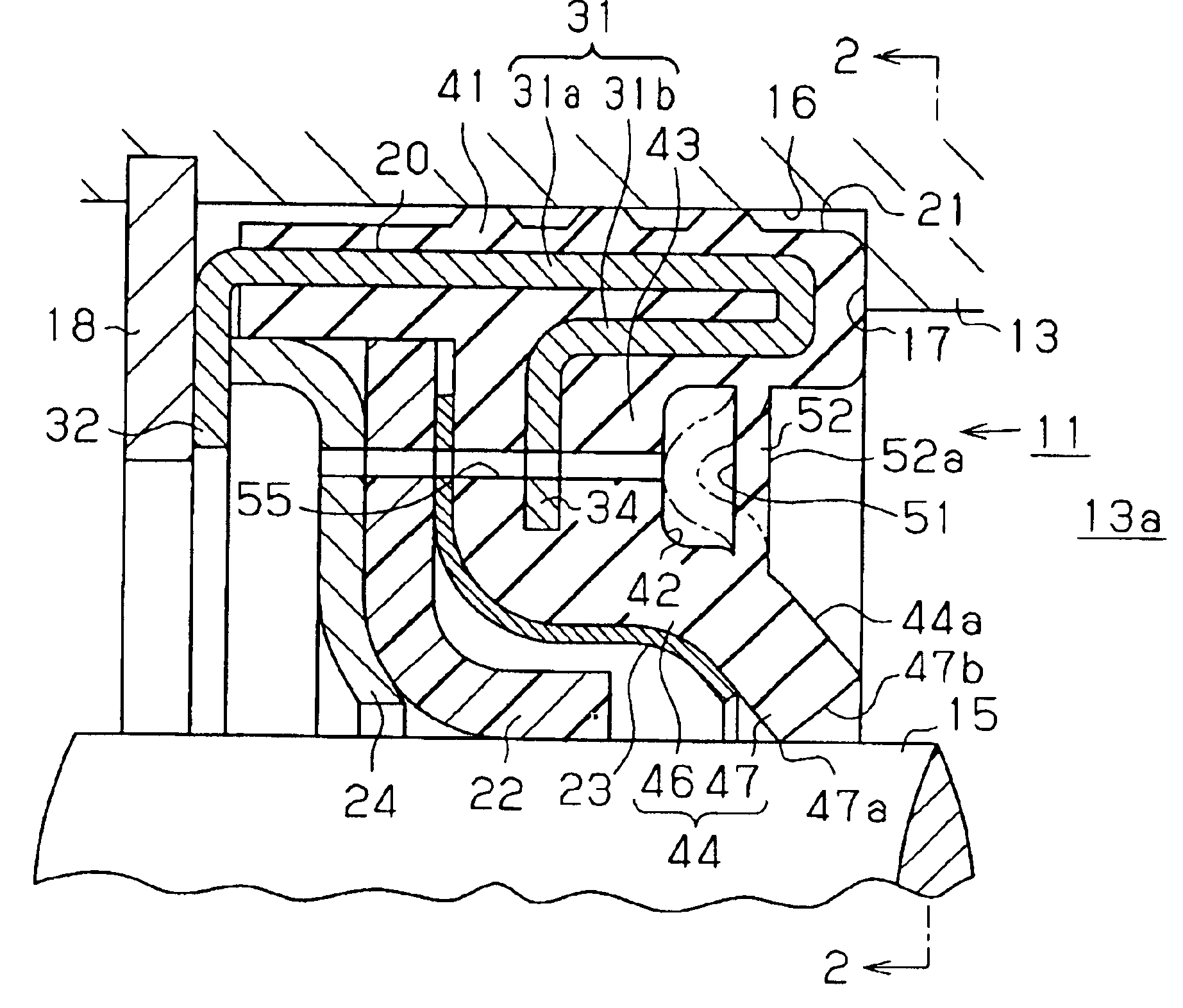
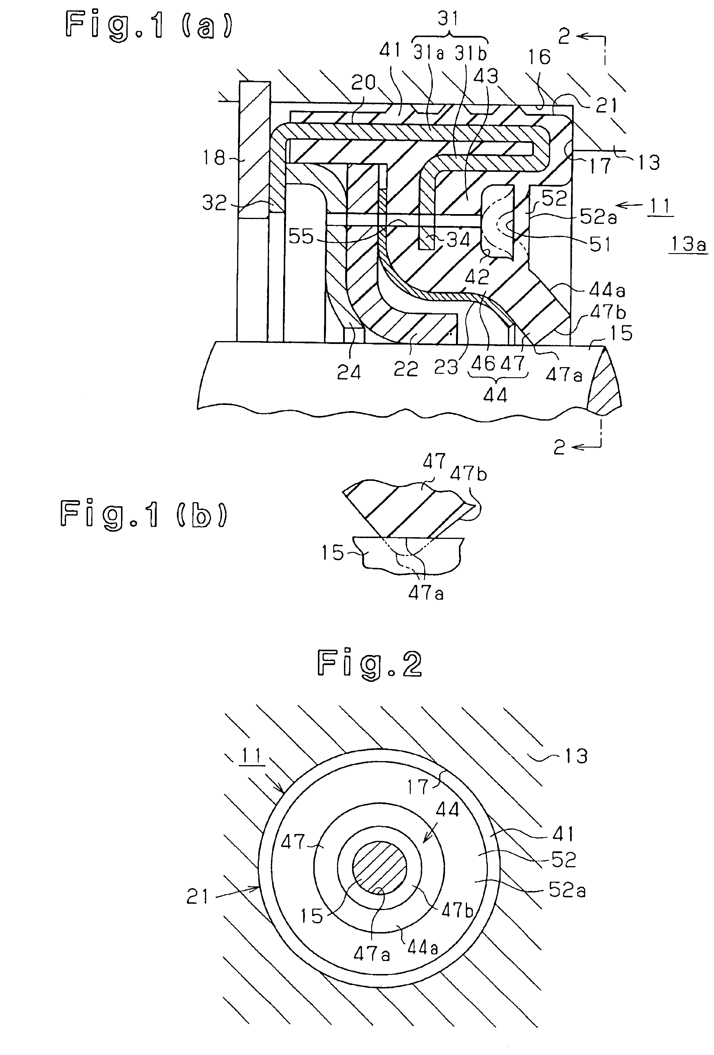
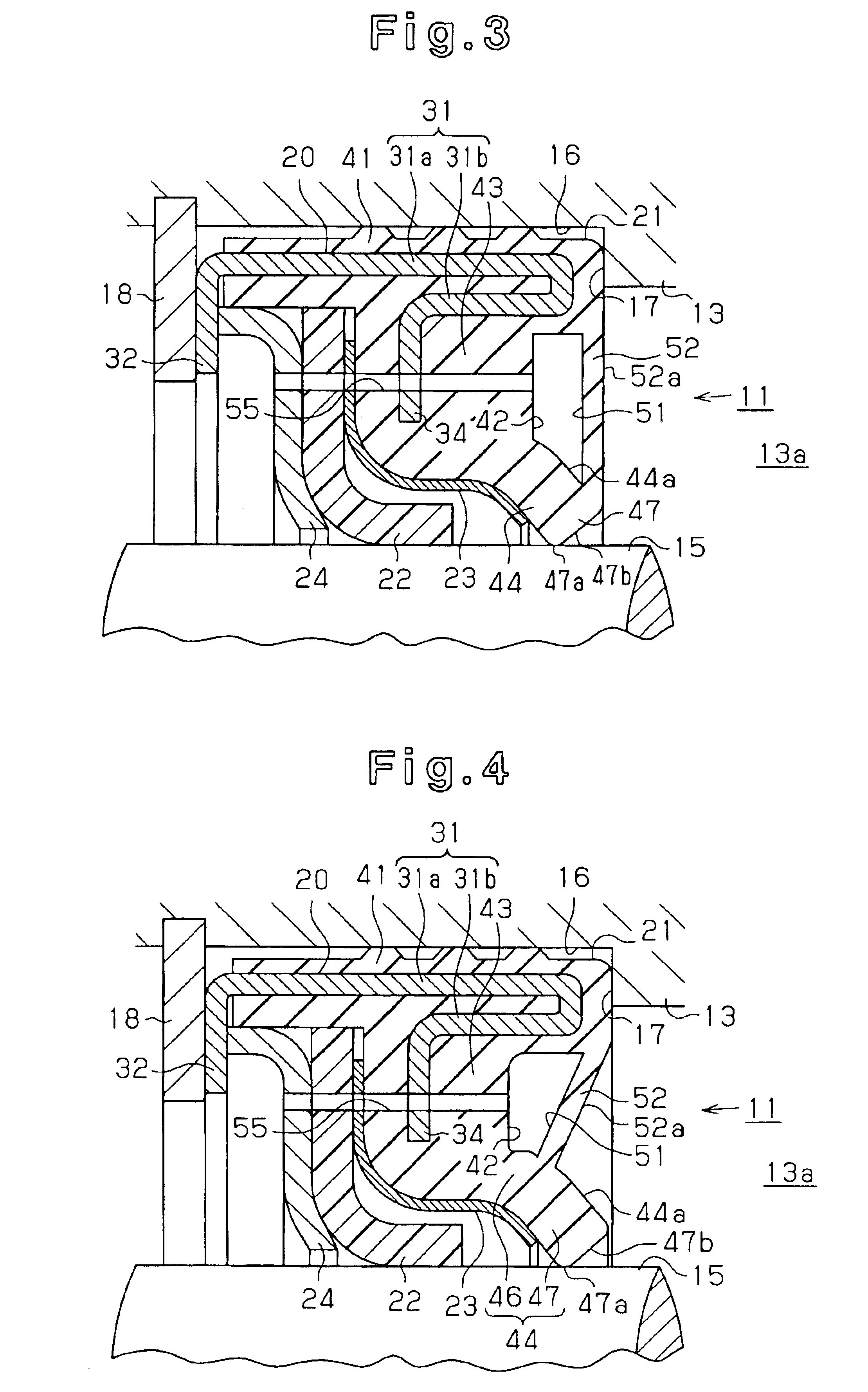
[0049]Therefore, the pressure in the interior space 13a, which acts on the pressure receiving surface 52a of the wall portion 52, not only elastically deforms the wall portion 52, but also pushes the entire wall portion 52 away from the rotary shaft 15. Therefore, compared to a case in which the pressure receiving surface 52a of the wall portion 52 is not inclined relative to a plane perpendicular to the axis of the rotary shaft 15 (for example, the first embodiment), tension acting on the lip portion 44 to loosen the force acting on the rotary shaft 15 is increased. As a result, even if the pressure in the interior space 13a is increased, the pressing force of the lip portion 44 applied to the rotary shaft 15 does not become excessive.

fourth embodiment

[0050]the present invention will now be described. As shown in FIG. 5, the hollow portion 51 is formed by an annular member 80 that is separately formed from the first sealing member 21.

[0051]That is, the annular member 80 is accommodated in the recess 42, which is formed in the first sealing member 21 and opens to the interior space 13a. The hollow portion 51 is defined in the annular member 80. The hollow portion 51 is annular and surrounds the rotary shaft 15. The annular member 80 functions as an outer wall that surrounds the hollow portion 51. The annular member 80 is made, for example, by joining the ends of a tube. A part of the annular member 80 that faces the inner surface of the recess 42 is shaped to conform to the inner surface of the recess 42, or to the main body coating portion 41, the flange coating portion 43, and the lip portion 44. A part of the annular member 80 that faces the inner surface of the recess 42 closely contacts and adhered to the inner surface of the...


PUM


Abstract

A shaft sealing assembly seals a rotary shaft of a refrigerant compressor with a first sealing member, which is a lip seal. The first sealing member has a hollow portion. As the pressure in the interior space of the compressor housing increases, an outer wall surrounding the hollow portion is elastically deformed. Accordingly, a lip portion of the first sealing member receives a tension that weakens a force pressing the lip portion against the rotary shaft. Therefore, the sealing assembly improves the durability of the lip portion and maintains a satisfactory property of the lip portion to follow displacement of the rotary shaft at the same time.

Description

BACKGROUND OF THE INVENTION[0001]The present invention relates to a shaft sealing assembly that is used in a refrigerant compressor installed in a refrigeration circuit and seals a rotary shaft of the compressor with a lip seal.[0002]In such a shaft sealing assembly, the internal pressure of a refrigerant compressor acts on a lip portion of the lip seal. The force with which the lip portion is pressed against the rotary shaft is adjusted in accordance with the internal pressure. This is referred to as “self-sealing” function. However, an excessively high internal pressure excessively increases the pressing force of the lip portion applied to the rotary shaft, which causes the lip portion to be abnormally worn.[0003]To prevent the abnormal wear, Japanese Laid-Open Patent Publication No. 2002-71028 discloses a configuration in which a space surrounding the back of a lip portion is filled with an annular elastic member. The elastic member receives an excessive internal pressure of a re...

Claims


Application Information

Patent Timeline
Patent Type & Authority Patents(United States)
IPC IPC(8): F16J15/16F16J15/32F16J15/3232
CPCF16J15/164F16J15/3284F16J15/3232F16J15/322
Inventor OSAKO, MASAMIYAMADA, TAKESHIMURASE, MASAKAZU
Owner TOYOTA IND CORP
Why Eureka
Try Eureka