Fiber optic guide pin

Inactive Publication Date: 2005-05-03
US CONEC
View PDF4 Cites 29 Cited by
  • Summary
  • Abstract
  • Description
  • Claims
  • Application Information

AI Technical Summary

Benefits of technology

[0005]In another aspect, the invention provides for a guide pin for aligning ferrules that includes an elongated cylindrical element, the elongated cylindrical element having a first end, a second end, a longitudinal axis therethrough, and a radius, the first end having a configuration to be insertable into a first ferrule, and the second end configured to engage an opening in a second ferrule, the second end having a smooth, continuous surface and a point at a p

Problems solved by technology

However, each of the prior art guide pins have an issue with either causing guide hole wear, skiving of the holes

Method used


Image

  • Fiber optic guide pin
  • Fiber optic guide pin
  • Fiber optic guide pin

Examples


first embodiment

[0021]a fiber optic guide pin 50 according to the present invention is illustrated in FIG. 5. The guide pin 50 is similar to the other guide pins (including its general structure), except that the second end 52 has a generally smooth, continuous surface 54. The second end 52 of guide pin 50 has a shape that corresponds generally to a parabola. As such, the surface of the second end 52 is smooth, meaning that it has no discontinuities as did the guide pins 10,25 (as at points P) due to the chamfer. A parabola's general equation is x2=−4py, where x is radial distance from the longitudinal axis (see FIG. 8) and y is the distance along the longitudinal axis of the pin, with the second end being the origin. However, since the origin of the parabola is taken to be the center of the pin at the second end 52, i.e., along longitudinal axis 56 through the center of the pin, then the above equation becomes y=r2 / 4 p, where r is the radius of the guide pin and variable p is preferably about 0.06...

second embodiment

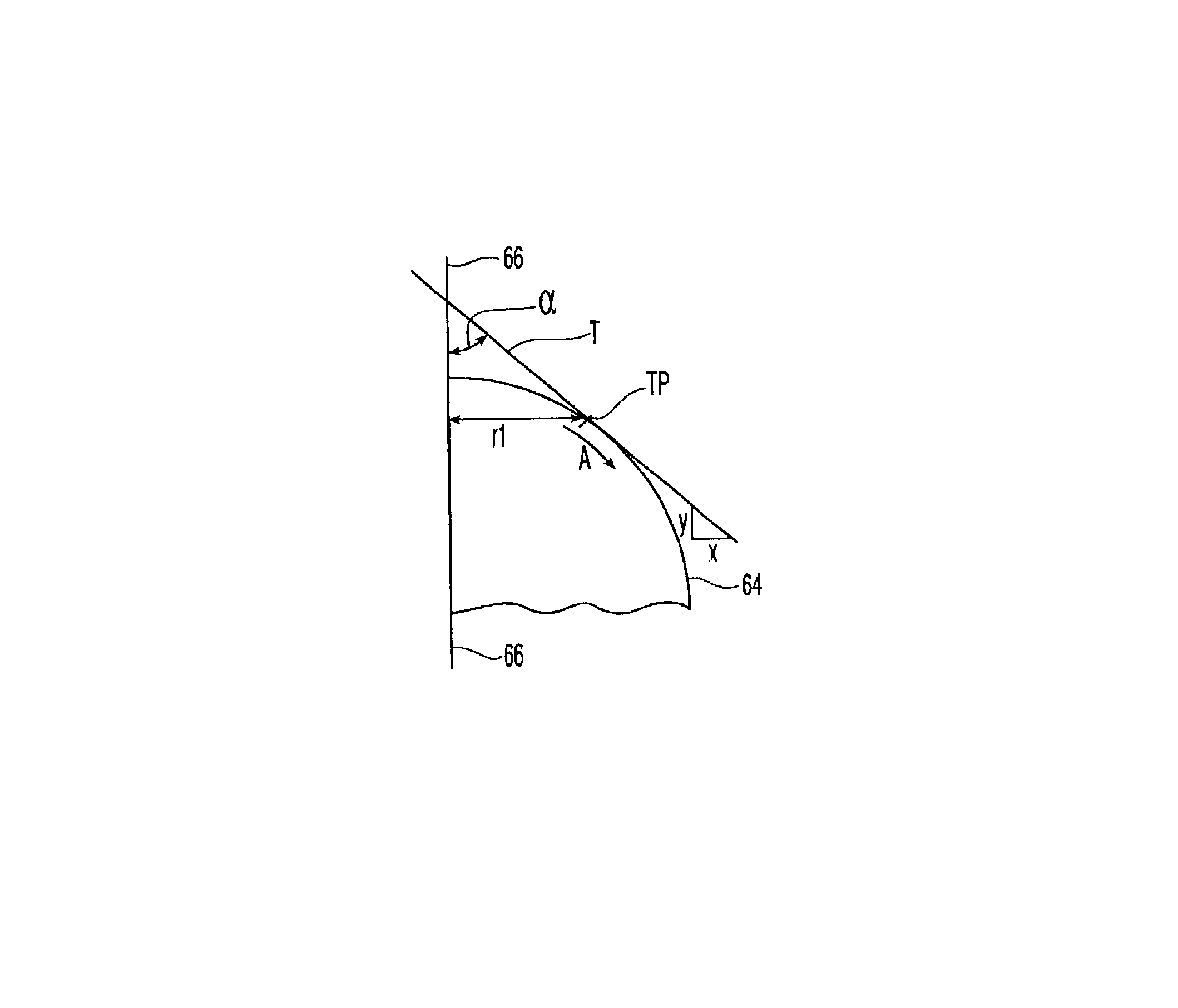
[0022]a fiber optic guide pin 60 according to the present invention is illustrated in FIG. 6. This embodiment of fiber optic guide pin 60 is similar to that of fiber optic guide pin 50, except that the second end 62, which also has a generally smooth, continuous surface 64, generally corresponds to an ellipse. The general equation for an ellipse is

x2b2+y2a2=1.

Again, if the center of the pin along the longitudinal axis 66 is taken to be the origin, then the equation for the ellipse and the surface 64 becomes

y=b1-(x⁢ / ⁢a)2-a

where 1.00≦2a≦1.20 mm and where 0.69≦b≦0.70 mm. Similar to fiber optic guide pin 50, the surface 64 is more streamlined than a simple radius and allows for less wear and skiving of the guide hole.

[0023]Another embodiment of a fiber optic guide pin according to the present invention is also illustrated in FIG. 7. Fiber optic guide pin 70 is similar to those in FIGS. 5 & 6, but instead of having a completely smooth, continuous surface that completely covers the second...


PUM


Abstract

A fiber optic guide pin is provided that has an end portion that is smooth and continuous. The smooth and continuous portion may be shaped to approximate an ellipse or a parabola. The end portion may also have a generally flat portion that is surrounded by the smooth and continuous portion.

Description

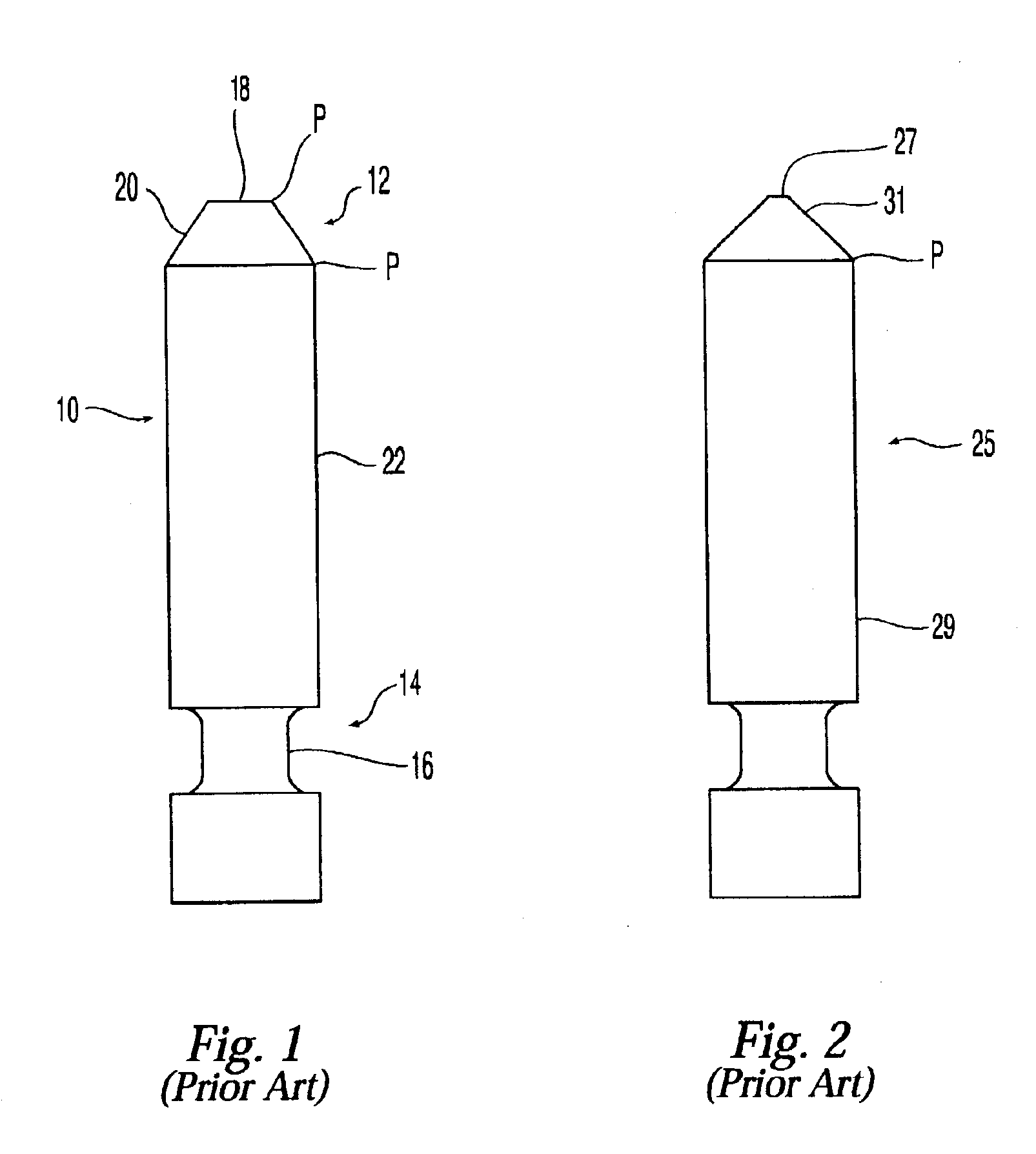
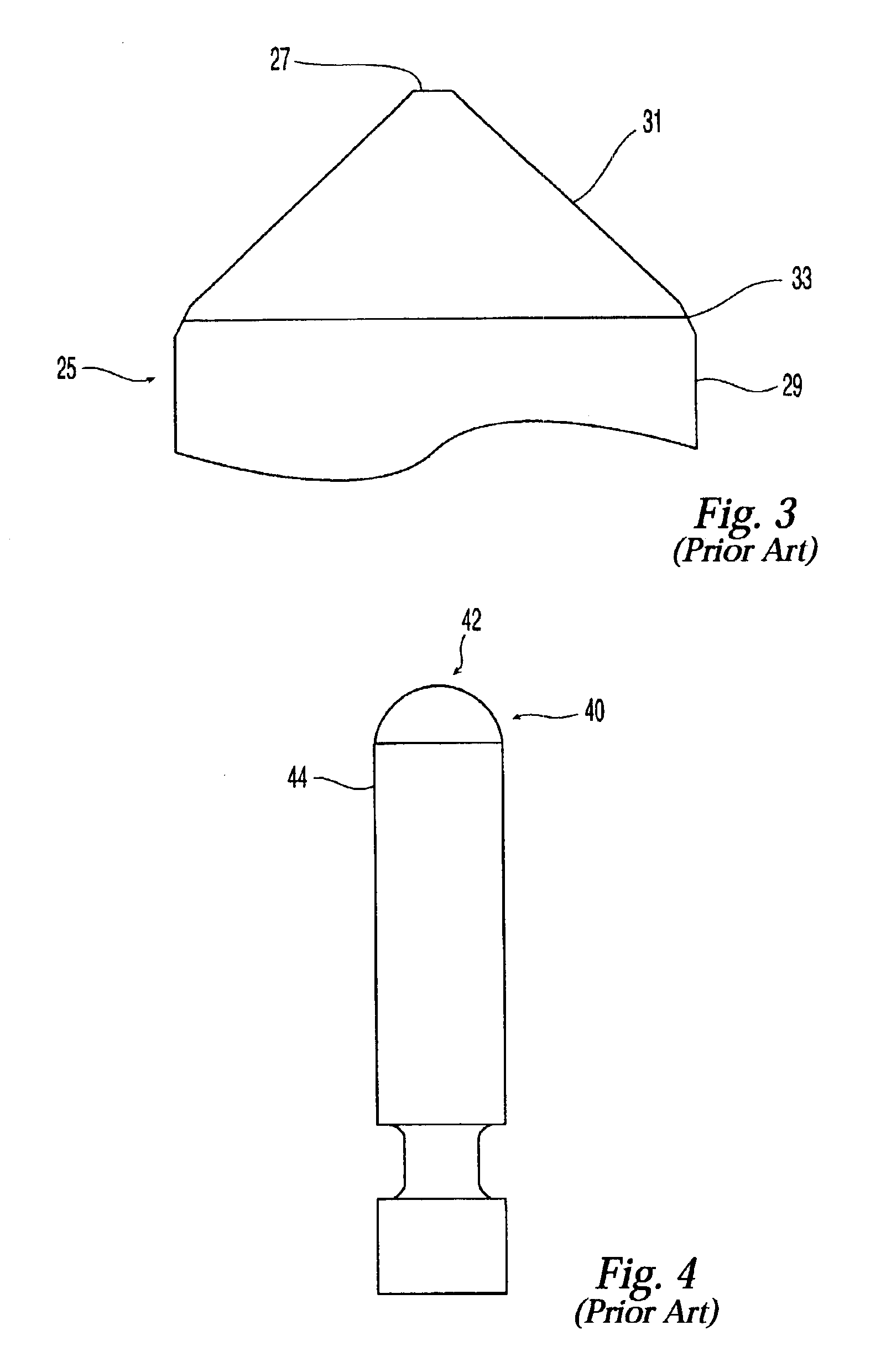
[0001]The present invention relates to a fiber optic guide pin, and more particularly, a fiber optic guide pin that reduces guide hole wear in fiber optic connectors with a smooth shape.[0002]There are prior art guide pins including, for example, guide pins that are chamfered—both single and double chamfered, and those with a simple radius. However, each of the prior art guide pins have an issue with either causing guide hole wear, skiving of the holes, or guide pins that do not easily position themselves into the guide hole with minimal damage to the guide hole.[0003]Accordingly, the present invention is directed to a fiber optic guide pin that substantially obviates one or more of the problems and disadvantages in the prior art. Additional features and advantages of the invention will be set forth in the description that follows, and in part will be apparent from the description, or may be learned by practice of the invention. The objectives and other advantages of the invention w...

Claims


Application Information

Patent Timeline
IPC IPC(8): G02B6/38G02B6/36
CPCG02B6/3882
Inventor BROWN, MATTHEW A.GRAHAM, JOSEPH L.ADAM, NARCIS
Owner US CONEC
Why Eureka
Try Eureka