Method of producing a vehicle steering wheel as well as a vehicle steering wheel

a technology of vehicle steering and production method, which is applied in the direction of steering control, controlling member, mechanical control device, etc., can solve the problems of complex foam encapsulation process, complex application and manufacture of thick rubber covering, which has a profiled cross-section, and achieves the effect of pleasing to the driver to grip

Inactive Publication Date: 2005-05-10
TRW AUTOMOTIVE SAFETY SYST
View PDF17 Cites 10 Cited by
  • Summary
  • Abstract
  • Description
  • Claims
  • Application Information

AI Technical Summary

Benefits of technology

[0003]The object of the invention is to provide a method that allows the production of inexpensive steering wheels which, especially haptically, are still pleasant for the driver to grip. Moreover, a vehicle steering wheel offering these advantages is to be provided.

Problems solved by technology

The foam-encapsulation procedure is complex and requires precise foaming molds.
However, the application and manufacture of this thick rubber covering, which has a profiled cross-section, are complex.

Method used


Image

  • Method of producing a vehicle steering wheel as well as a vehicle steering wheel
  • Method of producing a vehicle steering wheel as well as a vehicle steering wheel
  • Method of producing a vehicle steering wheel as well as a vehicle steering wheel

Examples


third embodiment

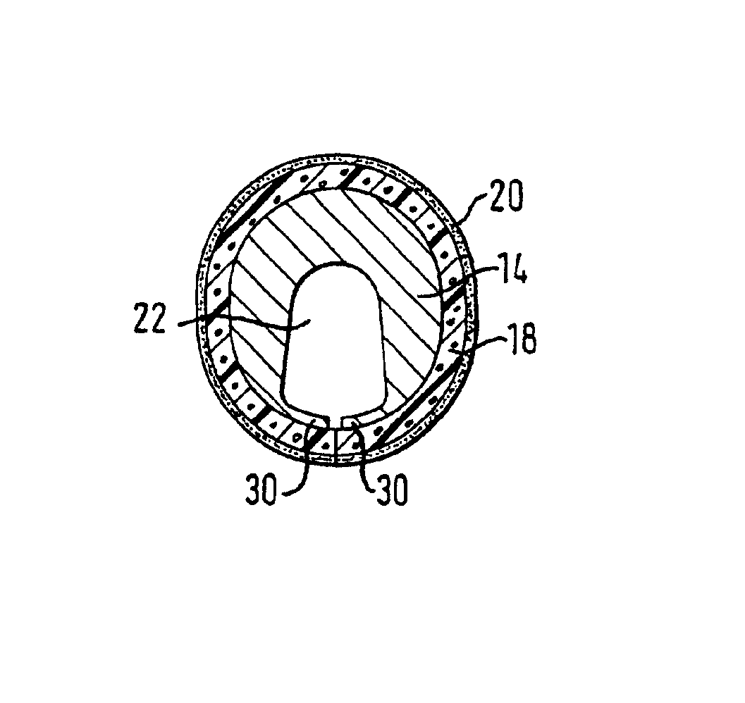
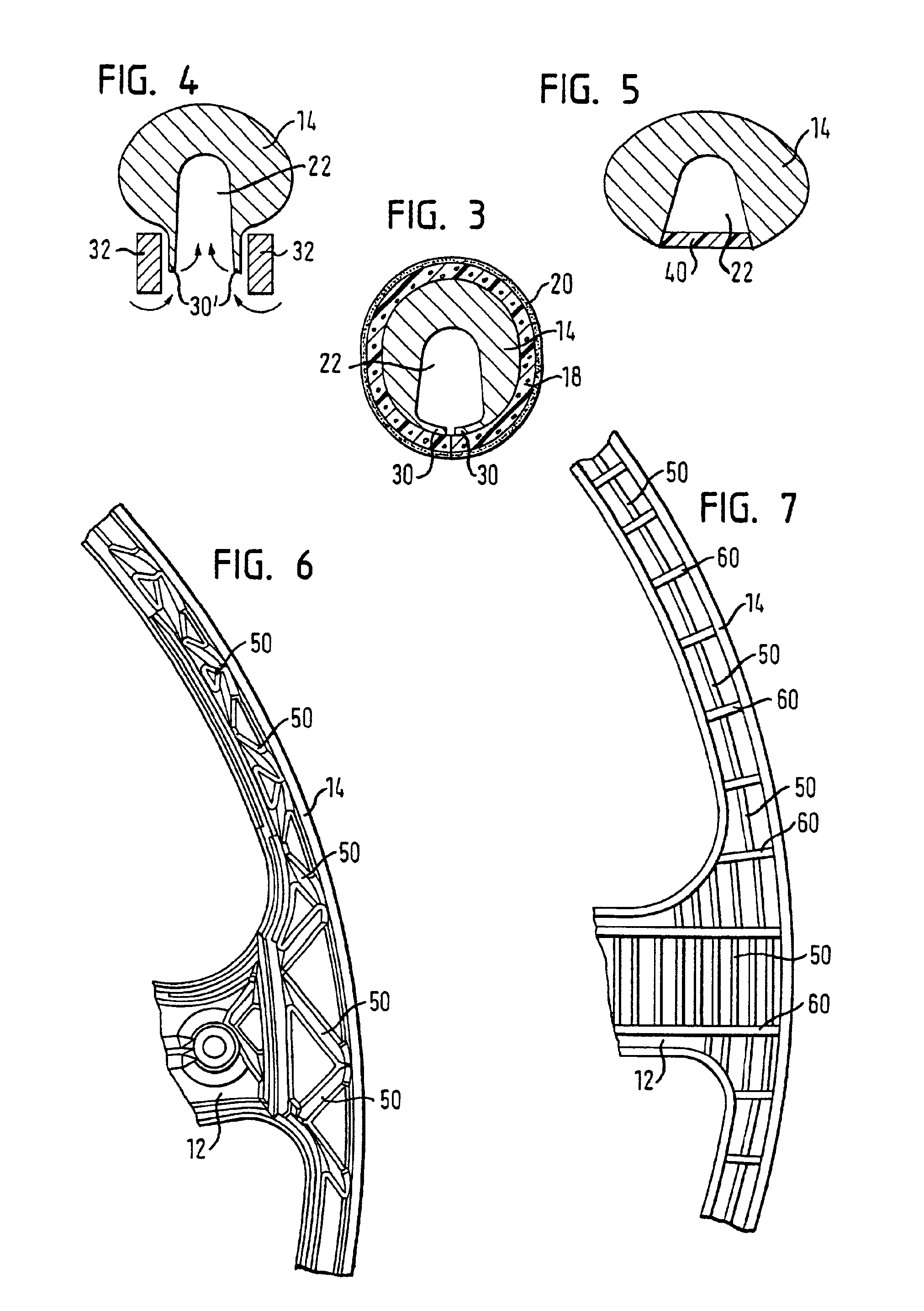
[0032]FIG. 3 shows a cross-section of a third embodiment through the steering wheel rim. Unlike the first two embodiments, the recesses 22 here are at least partially covered by small projections 30 on which the intermediate layer 18 rests. In this manner, wider recesses can be provided which nevertheless cannot be felt from the outside. The possibility of using wider recesses leads to a greater design freedom in terms of the variation of the weight and the tendency to vibrate.

[0033]The projections 30 can be easily obtained without an additional working step in that, during the injection-molding or casting, projections 30 are formed on the steering wheel rim 14 adjacent to the recesses 22 and then are deformed. FIG. 4 shows a steering wheel blank with formed-on projections 30′ that extend approximately radially from the steering wheel rim. After the forming procedure, the steering wheel blank is placed into a deburring press that is indicated here by two punches 32. The punches 32 b...

sixth embodiment

[0036]FIG. 7 shows a bottom view of a steering wheel rim blank for a steering wheel according to a Here too, cross-webs 50 are used, but in this case they run in the circumferential direction and intersect radial webs 60 at regular intervals.

[0037]In the fifth as well as in the sixth embodiment, on the one hand, a suitable arrangement and dimensioning of the cross-webs 50 or else of the cross-webs 50 and the radial cross-webs 60 can influence the weight and the vibration tendency of the steering wheel rim 14 in the desired manner and, on the other hand, the size of the hollow spaces formed can be set in such a way that they cannot be felt from the outside. If desired, the projections known from the third embodiment or the inserts known from the fourth embodiment can also be used to cover the recesses formed between the webs. The webs can then serve as supports for the projections or inserts.


PUM


Abstract

The invention relates to a method of producing a vehicle steering wheel. The method comprises the following steps: a) a one-piece steering wheel skeleton having a hub, at least one spoke and a steering wheel rim is produced by one of casting and injection-molding, b) an intermediate layer made of soft foam is glued directly onto the steering wheel rim and c) the intermediate layer is covered with leather in that the leather is glued directly onto the intermediate layer. As an alternative working step, a cover consisting of an inner intermediate layer made of soft foam with an outer covering made of leather is glued with an inside directly onto the steering wheel rim. The invention further relates to a vehicle steering wheel produced by one of the methods.

Description

TECHNICAL FIELD[0001]The invention relates to a method of producing a vehicle steering wheel as well as to a vehicle steering wheel produced by such a method.BACKGROUND OF THE INVENTION[0002]Vehicle steering wheels normally comprise a one-piece steering wheel skeleton having a hub, at least one spoke and a steering wheel rim. The skeleton of metal is foam-encapsulated in the area of the steering wheel rim and the spokes. The foam-encapsulation procedure is complex and requires precise foaming molds. Moreover, the foam-encapsulated skeleton still has to undergo a finishing step. German published examined application DE-AS 1,912,534 discloses a steering wheel skeleton that is not foam-encapsulated, but rather that is provided with a thick rubber covering in the area of the rim. However, the application and manufacture of this thick rubber covering, which has a profiled cross-section, are complex.BRIEF SUMMARY OF THE INVENTION[0003]The object of the invention is to provide a method tha...

Claims


Application Information

Patent Timeline
IPC IPC(8): B62D1/06B62D1/04
CPCB62D1/06Y10T74/2087Y10T74/20834
Inventor MILTENBERGER, MICHAEL
Owner TRW AUTOMOTIVE SAFETY SYST
Why Eureka
Try Eureka