Spanning tree bridge and route change method using the same

a bridge and tree technology, applied in the field of bridges, can solve the problems of dangerous data frame transmission, inability to perform frame transmission from blocked ports, and inability to restore from communication interrupts, etc., to achieve the effect of speeding up the restoration from communication interrupts

Inactive Publication Date: 2005-05-10
ANRITSU CORP
View PDF8 Cites 39 Cited by
  • Summary
  • Abstract
  • Description
  • Claims
  • Application Information

AI Technical Summary

Benefits of technology

[0089]The present invention has been made in order to solve the foregoing problem. It is an object of the present invention to provide a spanning tree bridge capable of taking action immediately even in the case where a communication route change occur, and speeding up restoration from a communication interrupt.

Problems solved by technology

In addition, frame transmission from a blocked port is not performed at all.
In the meantime, it is very dangerous to perform data frame transmission before all the bridges over a network enters a normal state after configuration (reconfiguration) of a spanning tree has been started.
If spanning tree reconfiguration occurs, a host position changes, and the contents of an old learning table may be incorrect.
However, in such conventional technique of reconfiguring a spanning tree, there has been a problem that, after a network failure has been detected, a certain time is required for opening such blocked port to enable communication between node “n1” connected to bridge B and node “n2” connected to bridge C; and restoration from a communication interrupt is slow, which causes lowered communication efficiency.

Method used


Image

  • Spanning tree bridge and route change method using the same
  • Spanning tree bridge and route change method using the same
  • Spanning tree bridge and route change method using the same

Examples


Embodiment Construction

[0142]Reference will now be made in detail to the presently preferred embodiments of the invention as illustrated in the accompanying drawings, in which like reference numerals designate line or corresponding parts.

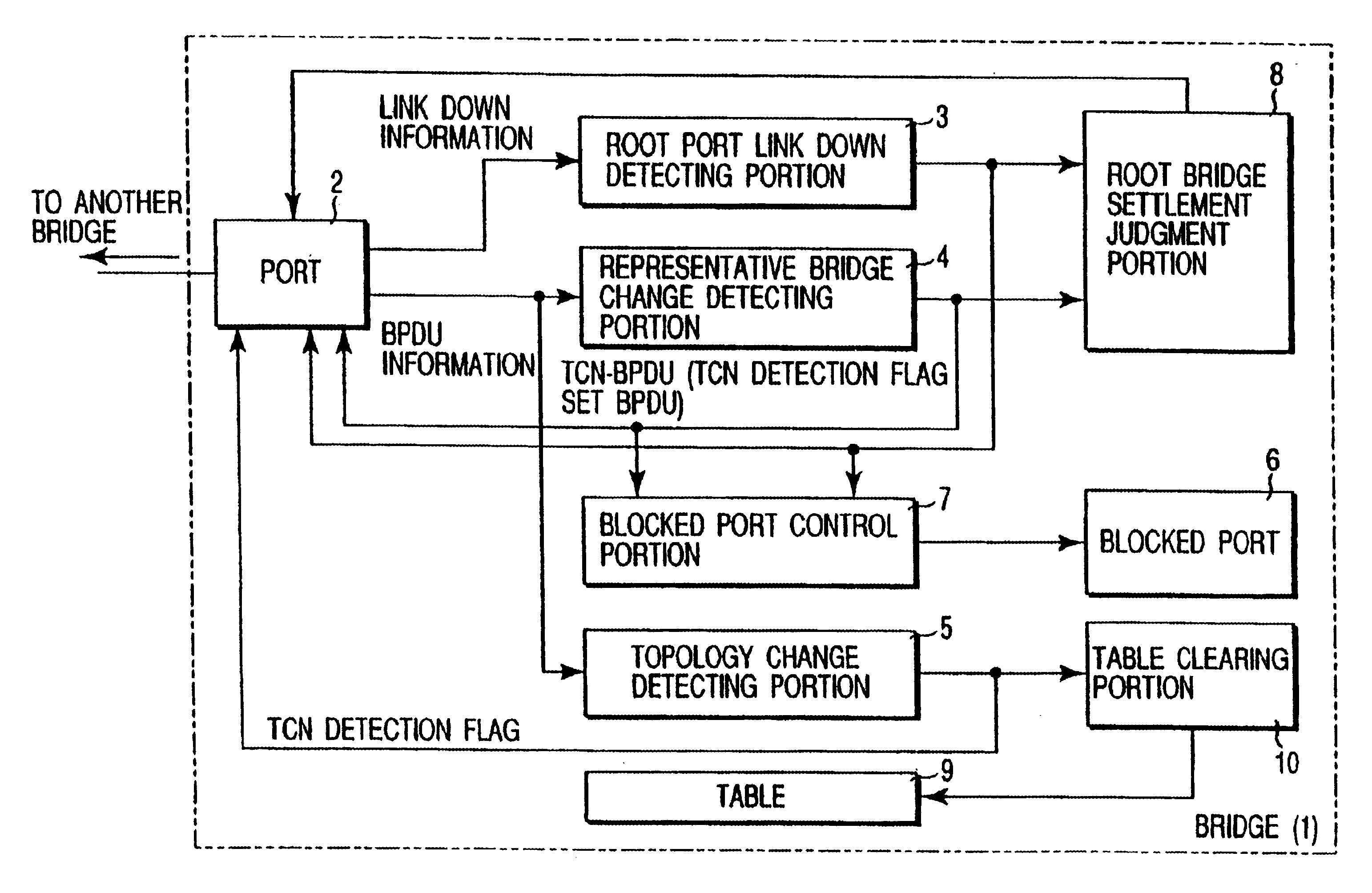
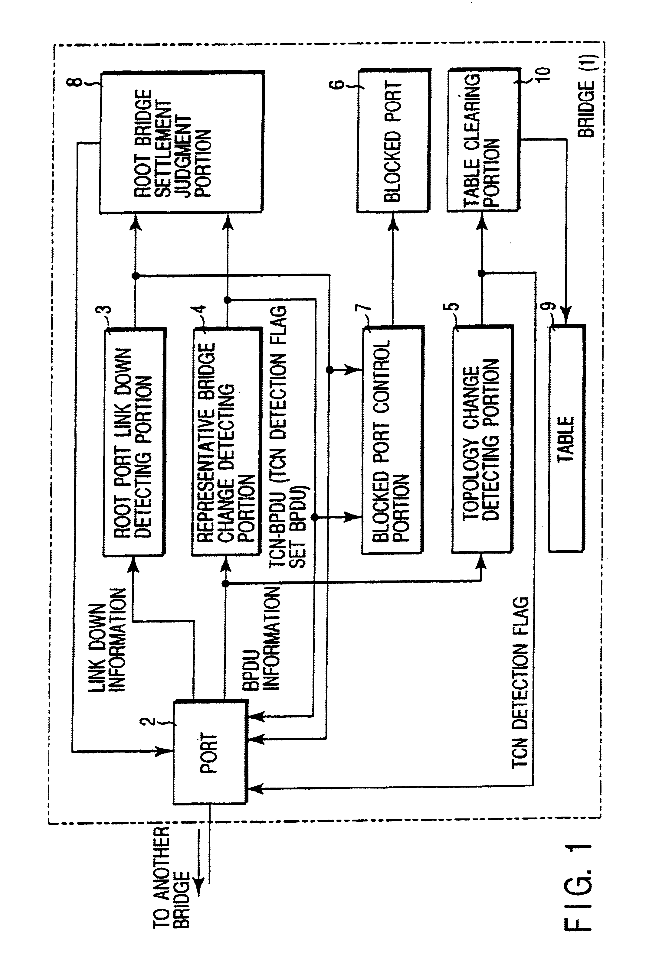
[0143]FIG. 1 is a functional block diagram schematically illustrating an internal configuration of a spanning tree bridge according to the present invention.

[0144]As shown in FIG. 1, a spanning tree bridge 1 comprises: a port 2 connected to another bridge; a link down detecting portion 3; a representative bridge change detecting portion 4; a topology change detecting portion 5; a blocked port 6; a blocked port control portion 7; a root bridge settlement judgment portion 8; a table 9; and a table clearing portion 10.

[0145]The representative bridge used herein denotes a bridge relatively positioned at an upper stage in bridges connected to each other.

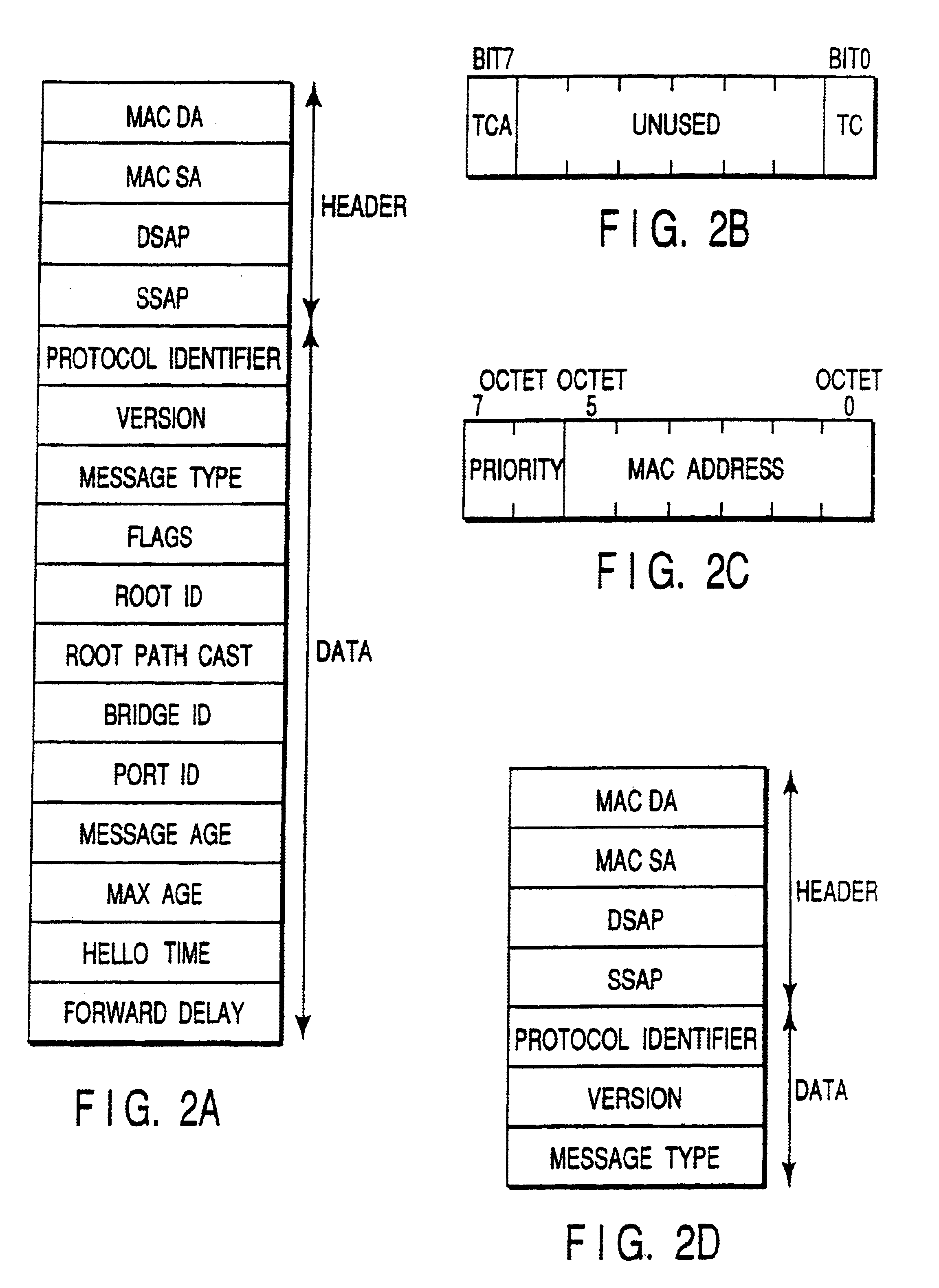
[0146]First, a BPDU transmitted to and received from bridges will be described with reference to FIG. 2A to FIG. 2C.

[0147]FIG...


PUM


Abstract

A controller changes a blocked port to a forwarding state when a link down or change of the representative bridge is detected and a receiving port of a bridge settled in the root bridge is a blocked port. When the bridge itself is not settled in a root bridge, a transmitter transmits to another bridge a TCN-BPDU that, when the bridge itself has received a BPDU inferior to itself BPDU, the representative bridge changes. A transmitter transmits to all other bridges a TC detection flag set BPDU when the bridge itself has received a TCN-BPDU and the bridge itself is settled in a root bridge. When the bridge itself is not settled in a root bridge and the bridge itself has received the TC detection flag set BPDU, such BPDU is transmitted in a direction other than root bridge direction, and the contents of a forwarding table of the bridge itself are deleted.

Description

CROSS-REFERENCE TO RELATED APPLICATIONS[0001]This application is based upon and claims the benefit of priority from the prior Japanese Patent Application No. 2000-067073, filed Mar. 10, 2000, the entire contents of which are incorporated herein by reference.BACKGROUND OF THE INVENTION[0002]The present invention relates to a spanning tree bridge and a route change method using the bridge. In particularly, the present invention relates to a spanning tree bridge employed in a network containing a redundant route caused by a plurality of bridges and a route change method using the bridge.[0003]In a network containing a redundant route caused by a plurality of bridges, a spanning tree protocol is employed for determining a route.[0004]For example, as shown in FIG. 7, assume a network over which LAN 1 and LAN 2 are connected to each other by means of a bridge A.[0005]Here, in the case of a network over which node “n1” such as personal computer is connected to LAN 1, and HUB 1 is connected...

Claims


Application Information

Patent Timeline
Patent Type & Authority Patents(United States)
IPC IPC(8): H04L12/56H04L12/28H04L12/46H04L12/54H04L45/18H04L45/24
CPCH04L45/02H04L45/28H04L45/22
Inventor ISHII, SHOJI
Owner ANRITSU CORP
Why Eureka
Try Eureka