Dc-dc power supply apparatus method for improving dc-dc power supply apparatus

a technology power supply apparatus, which is applied in the field of a method for improving dc-dc power supply apparatus, can solve the problems of low capability of low response speed of the supply voltage, and the transformer tends to howl and generate noise, so as to improve the ability to dynamically adjusting the output voltage of the entire circuit and achieve no longer restricted bandwidth

Inactive Publication Date: 2010-07-15
HUAWEI TECH CO LTD
View PDF9 Cites 34 Cited by
  • Summary
  • Abstract
  • Description
  • Claims
  • Application Information

AI Technical Summary

Benefits of technology

[0021]As seen from the foregoing technical solution, no isolation component like a transformer or an isolation optocoupler needs to participate in the process of adjusting the DC output voltage; instead, the control unit directly controls a rectifier circuit capable of transformation to adjust the DC output voltage. Because a transformer does not need to participate in the feedback loop, no noise is generated by the change of the working state of the transformer in the adjustment. In addition, because no isolation component like the isolation optocoupler needs to participate in the adjustment process, no delay is caused by the isolation component. Thus, the speed of response to the feedback signal is increased, the capability of dynamically adjusting the output voltage of the entire circuit is also improved, the bandwidth of the DC-DC power supply is no longer restricted by the isolation component and is wide enough, the response speed of the supply voltage is increased in the real-time adjustment of the output voltage, and the recovery speed of the supply voltage is increased when the load changes rapidly. Therefore, the dynamic performance of the DC-DC power supply is enhanced.

Problems solved by technology

1. While adjusting the output voltage of the power supply according to the signals collected by the sampling unit 101, the transformer T11 participates in the adjustment. In the adjustment, the working state of the transformer T11 changes in each cycle. When the change frequency of the working state of the transformer T11 falls within the audio range, the transformer tends to howl and generate noises.
2. While adjusting the output voltage of the power supply according to the signals collected by the sampling unit 101, the signals transmitted through the isolation optocoupler 103 have a certain delay, which leads to a low capability of dynamically adjusting the output voltage of the entire circuit. Moreover, the inherent working bandwidth of the isolation optocoupler 103 is narrow, which leads to a relatively narrow system bandwidth of the isolation DC-DC high-frequency switch power supply. In the real-time adjustment of the output voltage, the response speed of the supply voltage is low. When the load changes rapidly, the recovery speed of the supply voltage is low.

Method used


Image

  • Dc-dc power supply apparatus method for improving dc-dc power supply apparatus
  • Dc-dc power supply apparatus method for improving dc-dc power supply apparatus
  • Dc-dc power supply apparatus method for improving dc-dc power supply apparatus

Examples


embodiment 1

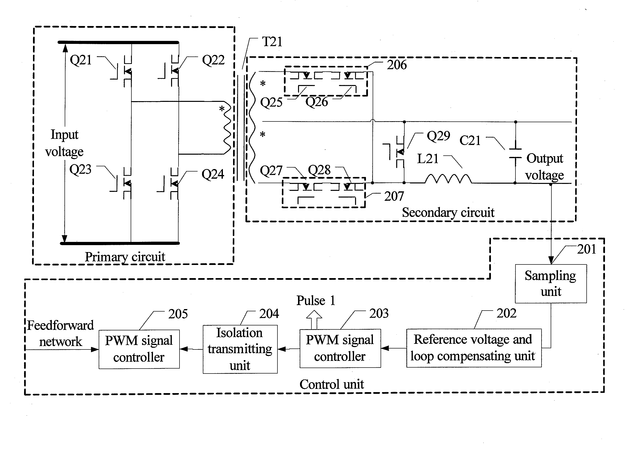
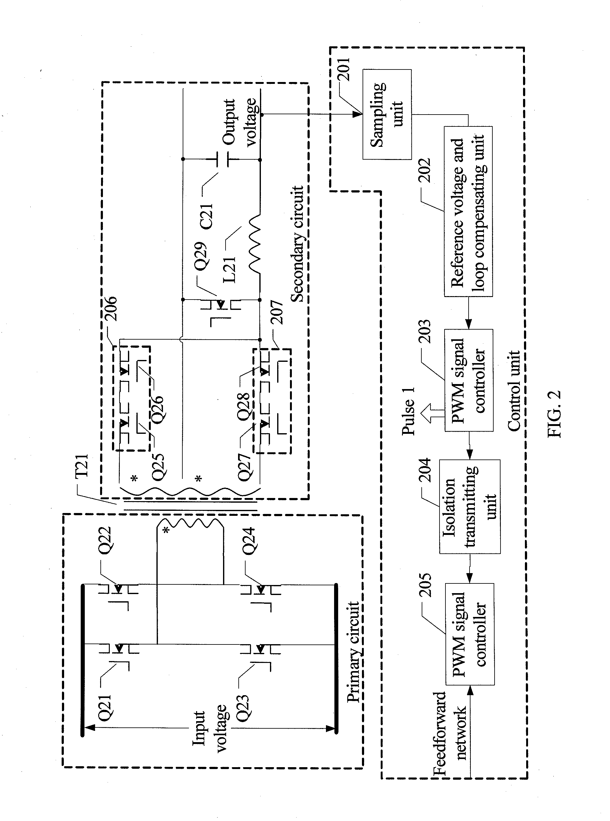
[0049]In the DC-DC power supply apparatus in the present invention, the primary circuit adopts a full-bridge topology, and the secondary winding of the transformer has a center tap. FIG. 2 is a circuit diagram of the apparatus.

[0050]The circuit includes: a primary circuit, a secondary circuit, and a control unit. The secondary winding of the isolation primary transformer T21 connected to the primary circuit and the secondary circuit has a center tap.

[0051]The circuit coupled to the primary winding of the isolation primary transformer T21 is referred as the transformer primary circuit. The MOS transistors Q21, Q22, Q23, and Q24 constitute two bridge arms of the transformer primary circuit. The structure of the primary circuit is a full-bridge topology structure.

[0052]Pulse signals of a constant duty ratio may be used to control the on / off state of the MOS transistors Q21, Q22, Q23, and Q24 of the primary circuit of the DC-DC power supply apparatus according to the actual application ...

embodiment 2

[0081]FIG. 6 is a circuit diagram of a DC-DC power supply apparatus of the present invention.

[0082]The circuit includes: a primary circuit, a secondary circuit, and a control unit. The secondary winding of the isolation primary transformer T21 connected to the primary circuit and the secondary circuit has a center tap.

[0083]The circuit coupled to the primary winding of the isolation primary transformer T61 is referred as the transformer primary circuit. The MOS transistors Q61, Q62, Q63, and Q64 constitute two bridge arms of the transformer primary circuit. The structure of this primary circuit is referred as a full-bridge topology structure.

[0084]Pulse signals of a constant duty ratio may be used to control the on / off state of the MOS transistors Q61, Q62, Q63, and Q64 of the primary circuit of the DC-DC power supply apparatus according to the actual application conditions, or a primary circuit may be used to control the on / off state for the purpose of fine tuning.

[0085]By control...

second embodiment

[0117]If more independent output voltages are required, more windings of the transformer may be added. For each added winding, a pair of independent output voltages may be added. The mode of obtaining the output voltages by adding windings is similar to the mode of implementing the DC-DC power supply apparatus herein.

[0118]Based on the embodiments of the present invention, improvement may be made for other DC-DC power supplies that use a primary traditional topology structure, namely, the DC-DC power supplies whose circuit structure can be split by the isolation component into a primary circuit and a secondary circuit, for example, the DC-DC power supplies that employ a single-ended forward circuit, a push-pull circuit, or a half-bridge circuit.


PUM


Abstract

A Direct Current to Direct Current (DC-DC) power supply apparatus includes: a transformer; a transformer primary circuit; a transformer secondary circuit, which includes a rectifier circuit capable of transformation and configured to convert a square wave voltage output by the transformer into a DC output voltage; and a control unit, which controls the transformer secondary circuit to stabilize the DC output voltage into a required value according to the DC output voltage.

Description

CROSS-REFERENCE TO RELATED APPLICATIONS[0001]This application is a continuation of International Application No. PCT / CN2008 / 071390, filed on Jun. 20, 2008, which claims priority to Chinese Patent Application No. 200710151684.5, filed on Sep. 26, 2007, both of which are hereby incorporated by reference in their entireties.FIELD OF THE INVENTION[0002]The present invention relates to electronic technologies, and in particular, to a Direct Current to Direct Current (DC-DC) power supply apparatus and a method for improving a DC-DC power supply apparatus.BACKGROUND OF THE INVENTION[0003]A common isolation DC-DC high-frequency switch power supply, as a DC converter, usually adopts a full-bridge isolation transformation topology. FIG. 1 shows a circuit structure of an isolation DC-DC high-frequency switch power supply.[0004]This circuit includes: a primary circuit, a secondary circuit, and a control circuit. As shown in FIG. 1, the circuit coupled to the primary winding of an isolation prim...

Claims


Application Information

Patent Timeline
Patent Type & Authority Applications(United States)
IPC IPC(8): H02M3/335
CPCY02B70/1475H02M3/33592Y02B70/10
Inventor LIU, ZHIHUA
Owner HUAWEI TECH CO LTD
Why Eureka
Try Eureka