Wheel end assembly high-temperature warning system

Inactive Publication Date: 2005-05-17
PRESSURE SYST INT LLC
View PDF9 Cites 54 Cited by
  • Summary
  • Abstract
  • Description
  • Claims
  • Application Information

AI Technical Summary

Benefits of technology

[0004]A further object of the present invention is the provision of a wheel end assembly having a high temperature warning system including an air pressure supply, a normally closed valve connected between the inside and outside of the pressure supply, a heat sensitive control connected to and actuating the valve upon a predetermined temperature in which the control is mounted adjacent the wheel assembly for measuring the temperature of the wheel assembly, and a warning system connected to the pressure supply for actuation upon opening of the valve.
[0008]Still a further object of the present invention is in which a vehicle having an automatic tire inflation system, is for providing air to a rotating tire on a wheel hub mounted on bearings on a hollow axle, is connected to an air pressure supply for supplying air to the inside of the axle, a rotary connection in communication between the tire and the air inside of the axle, of the combination of a high temperature warning system comprising a normally closed valve connected between the inside and outside of the axle in communication with the air in the axle. A heat sensitive control is connected to and actuating the valve open upon a predetermined temperature and said control is mounted adjacent the wheel assembly for measuring the temperature of the wheel assembly and axle, and a warning system is connected to the air supply for actuation upon opening of the valve. In one embodiment the hollow axle is closed at the ends with a plug and a heat sensitive pressure barrier is positioned in each plug. As an alternative, one or more heat sensitive pressure barriers may be positioned in the axle adjacent the bearings or brakes in the wheel assembly. And in another alternative the air pressure supply includes an air supply tubing positioned in the axle and connected to one or more heat sensitive pressure barriers. Again, the pressure barriers may be positioned in a plug at each end of the hollow axle or positioned adjacent the wheel bearings and brakes are connected in the axle.

Problems solved by technology

It is also the possibility, due to the intense heat caused by any failure that the wheel can detach from the axle.

Method used


Image

  • Wheel end assembly high-temperature warning system
  • Wheel end assembly high-temperature warning system
  • Wheel end assembly high-temperature warning system

Examples


Embodiment Construction

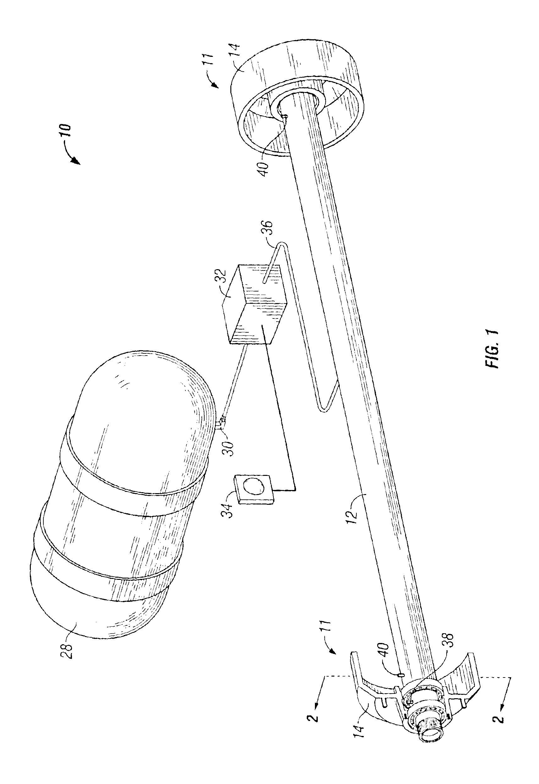
[0020]Referring now to FIGS. 1 and 2, the reference numeral 10 generally indicates the high temperature warning system of the present invention as installed in a vehicle having an axle 12 and a spindle 13 portion thereof. A wheel assembly 11 includes a hub 14 which rotates on inner and outer bearings 16 and 18, respectively, which rotate on inner and outer bearing races, respectively, 20 and 22, and extends through a brake drum 24 and supports a tire and wheel 26. As has been indicated in the event of a bearing 16 or 18 or a brake 24 failure, the temperature in the bearings 16 and 18, the brake drum 24 and spindle 13 area may reach a temperature to where the tires (not shown) on the tire and wheel 26 or lubricant (not shown) may ignite causing a fire. There is also the possibility because of the intense heat caused by such failures that the hub 14 and wheel and tire 26 may detach from the axle 12.

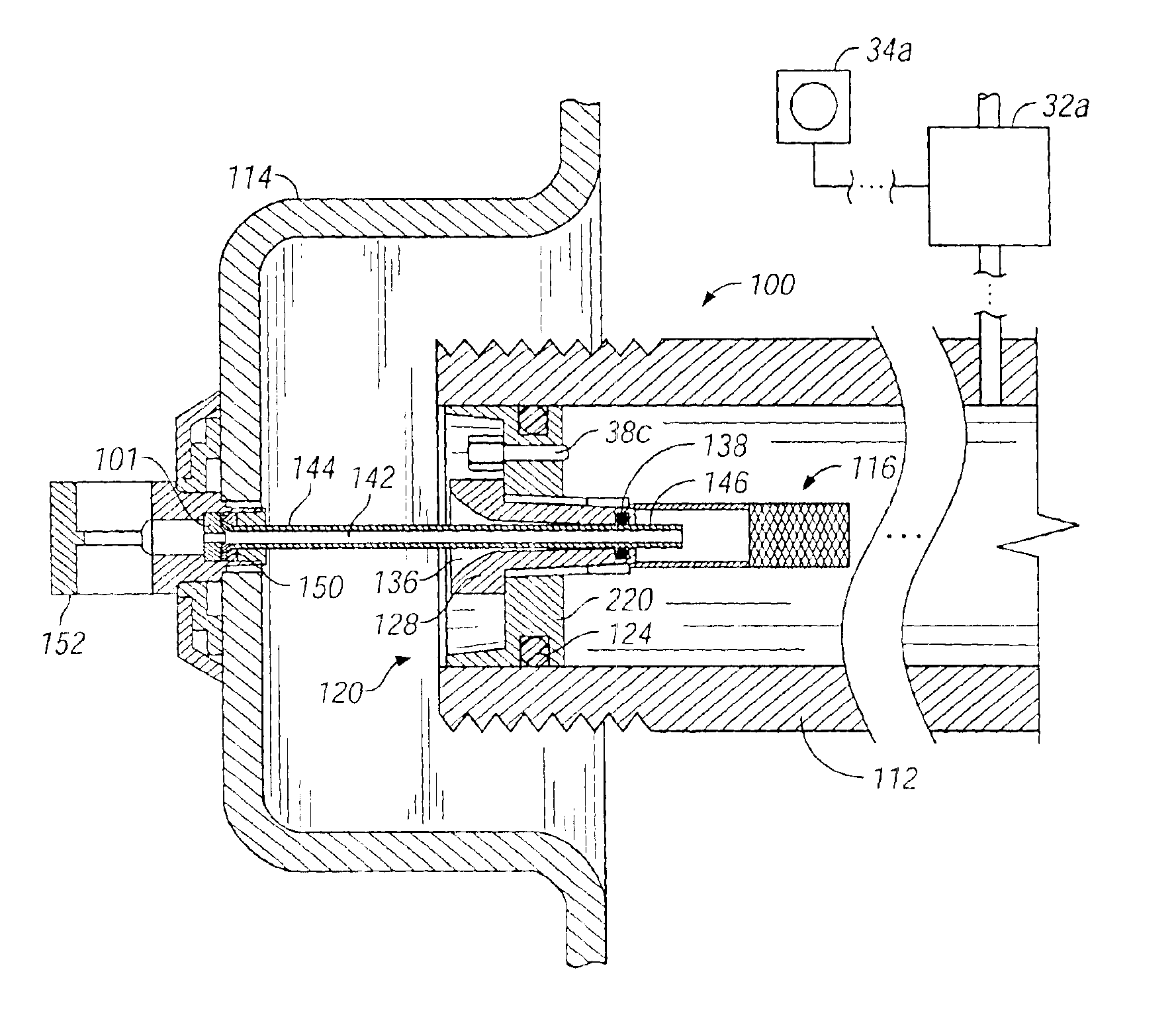
[0021]The temperature warning system 10 of the present invention includes an air pressu...


PUM

PropertyMeasurementUnit
temperatureaaaaaaaaaa
pressureaaaaaaaaaa
heat sensitiveaaaaaaaaaa

Abstract

The present invention is directed to a wheel end assembly having a high temperature warning system for giving a warning in the event that the temperature in the assembly reaches a predetermined value such as caused by hub bearing failure or a brake related failure. In one embodiment the system may be a stand-alone system for installation on any vehicle such as a trailer. In another embodiment the system may be combined with an automatic tire inflation system.

Description

BACKGROUND OF THE PRESENT INVENTION[0001]The present invention is directed to a wheel end assembly having a high temperature warning system for giving a warning in the event that the temperature in the assembly reaches a predetermined value such as by a hub-bearing failure or brake related failure. The system may be a stand-along system for installation on any vehicle such as a tractor trailer or in another embodiment may be a system combined with an automatic tire inflation system.[0002]In the event of a wheel end assembly bearing failure or brake related failure on a vehicle such as a tractor trailer, the temperature in the assembly and axle spindle area can reach a temperature to where the tires or lubricant may ignite causing the vehicle to burn or the wheel to lock up. It is also the possibility, due to the intense heat caused by any failure that the wheel can detach from the axle.BRIEF SUMMARY OF THE INVENTION[0003]The present invention is directed to a high temperature warnin...

Claims


Application Information

Patent Timeline
Patent Type & Authority Patents(United States)
IPC IPC(8): B61K9/00B61K9/04
CPCB60C23/003B61K9/04B60C23/20Y10T29/49826B60C23/00327B60C23/00336B60C23/00354B60C23/00363B60C23/002B60C23/009B60C23/02
Inventor HENNIG, MARK K.SONZALA, FRANK J.
Owner PRESSURE SYST INT LLC
Why Eureka
Try Eureka