

Microscope system
a microscope and system technology, applied in the field of microscope systems, can solve the problems of troublesome operation and difficult use of the conventional microscope system
- Summary
- Abstract
- Description
- Claims
- Application Information
AI Technical Summary
Problems solved by technology
Method used
Image

Examples
first embodiment
[0055]In a first embodiment, conditions of an image pickup operation of the image pickup element of the electronic camera is set to be optimum in accordance with the state of a microscope projection magnification or observation method (lighting conditions).
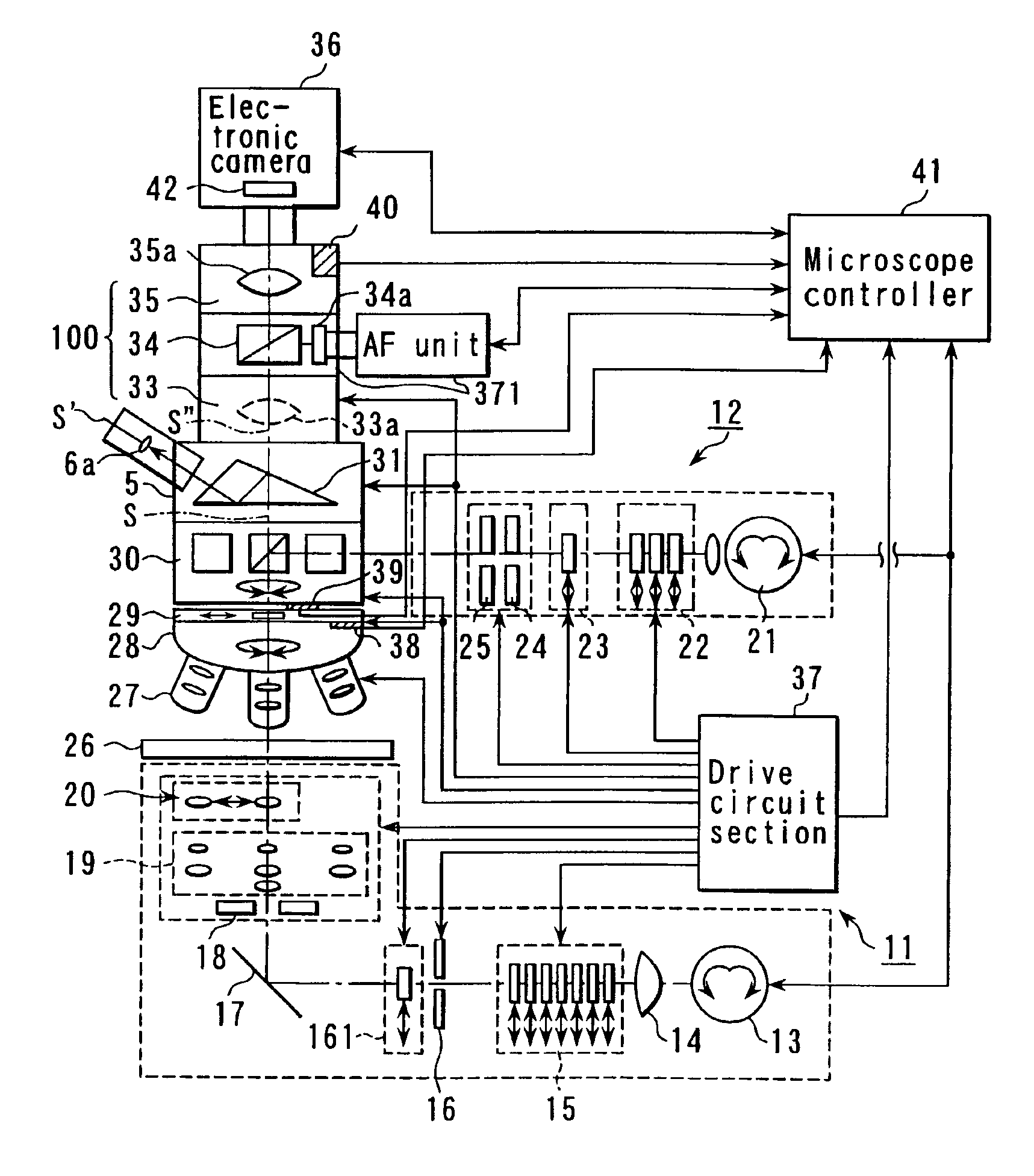
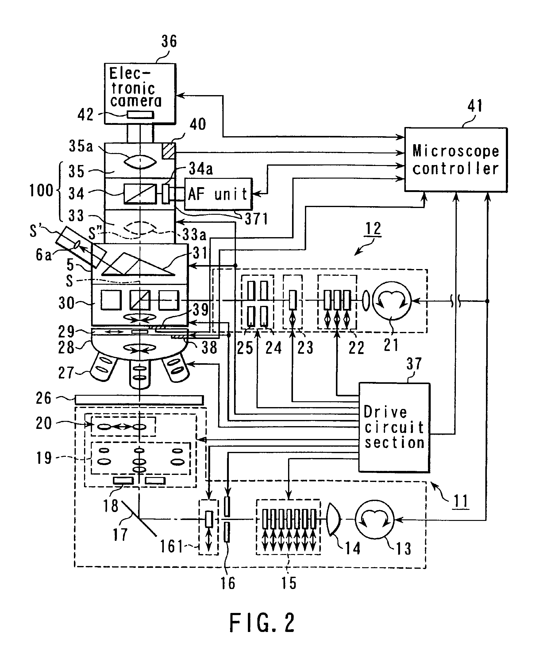
[0056]FIG. 5 is a diagram showing a constitution of the microscope and electronic camera according to the first embodiment. For the constitution of FIG. 5, a related part is extracted from the constitution shown in FIG. 3. Therefore, description of the constituting part is omitted.
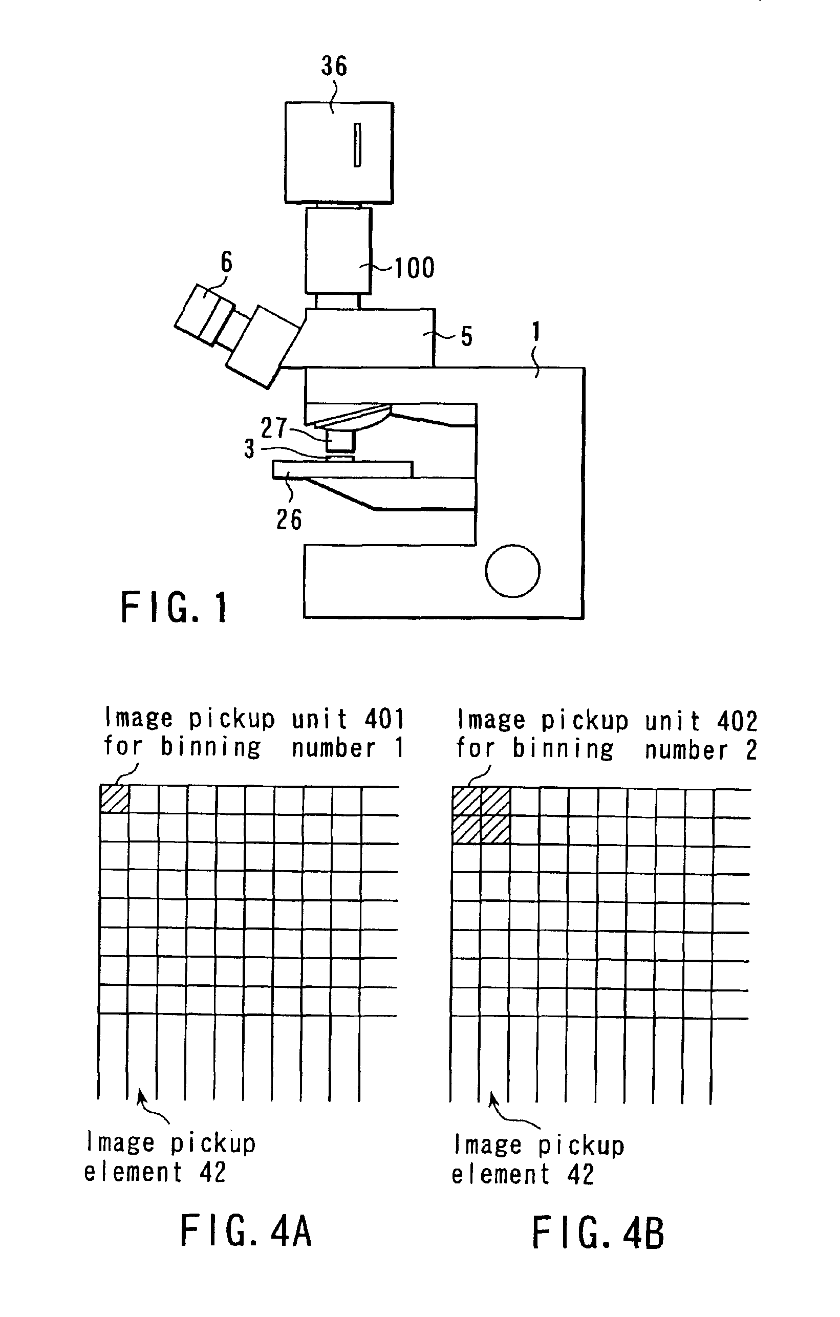
(1) State of Projection Magnification→Setting of binning number: The binning number is set in accordance with the state of the projection magnification.
[0057]First, when the observer instructs the microscope controller 41 via an operation section (not shown) to change an optical system magnification (projection magnification), the microscope controller 41 changes the magnification of the objective lens 27, and an intermediate magnification change ratio i...
modification example 1
[0067](1) Modification Example 1
[0068]The NA is obtained from the correspondence table of the optical system combination and NA, the resolution is obtained from the NA, and the binning number is obtained from a relation between the resolution and the CCD pixel pitch.
[0069]In this case, the following Table 3 is stored beforehand in the memory 48a of the controller 48. The controller 48 identifies the optical system combination by the information from the microscope controller 41 as described above, compares the combination with that in the stored table, and obtains NA of the light incident upon the electronic camera corresponding to the optical system combination.
[0070]
TABLE 3Correspondence table of opticalsystem combination and NAObjective444410. . .4040. . .Lens (times)Intermediate11221. . .11. . .Magnifica-tionChange(times)Photo12121. . .12. . .Eyepiece(times)NA0.040.020.020.010.04. . .0.020.01. . .
[0071]Subsequently, the controller 48 obtains the resolution R from the NA of the l...
modification example 2
[0073](2) Modification Example 2
[0074]When the image forming optical system of the microscope is constituted of the objective lens 27 and one type of image forming lens, the binning number is obtained from the correspondence table of the objective lens and binning number such as the following Table 4.
[0075]In this case, the following Table 4 is stored beforehand in the memory 48a of the controller 48. The controller 48 identifies the objective lens by the information from the microscope controller 41 as described above, compares the lens with that in the stored table and obtains the binning number.
[0076]
TABLE 4Correspondence table of objectivelens type and binning numberObjective410204060LensTimesTimesTimesTimesTimesBinning11122Number
PUM
 Abstract
Description
Claims
Application Information