
Holder for a concrete slurry hose

a technology for concrete slurry and hoses, which is applied in the direction of hoisting equipment, machine supports, other domestic objects, etc., can solve the problems of requiring substantial lifting force, affecting the quality of concrete slurry, etc., to achieve convenient and quick manipulation, reduce the effect of labor intensity

Inactive Publication Date: 2005-05-17
AYALA HENRY
View PDF6 Cites 8 Cited by
  • Summary
  • Abstract
  • Description
  • Claims
  • Application Information

AI Technical Summary

Benefits of technology

"The present invention is a holder for a slurry dispensing hose that allows for easy lifting and manipulation of the hose to fill openings in a wall. The holder is designed to be used with a conventional hose without any modifications. It is lightweight and can be easily moved in any direction. The holder is also cost-effective to manufacture and sell to consumers. The technical effects of the invention include improved efficiency and ease of use for slurry dispensing in construction projects."

Problems solved by technology

To fill the openings along an entire length of wall may take several minutes and maybe even hours.
Because of the weight and the time involved plus the fact that the dispensing of the slurry is constant, this procedure becomes quickly physically exhausting to the human.
However, a substantial lifting force is required each time the hose holder is moved to a new location since the human must not only lift the weight of the hose holder and the hose extending to the ground but also the weight of the slurry within both the hose holder and the hose that goes to the ground.
However, this precise shutting down of the flow very seldom occurs with a result that an over-filling occurs.
This over-filling results in the cement slurry flowing down along the outside surfaces of the wall which then requires that this portion of the wall must be cleaned.
There is no way to conveniently direct this flow in a different direction from this hose holder since the hose is not held by one's hand and the dispensing end of the hose holder is rigid and is designed to flow only in a downward direction into the openings of the blocks of the wall.

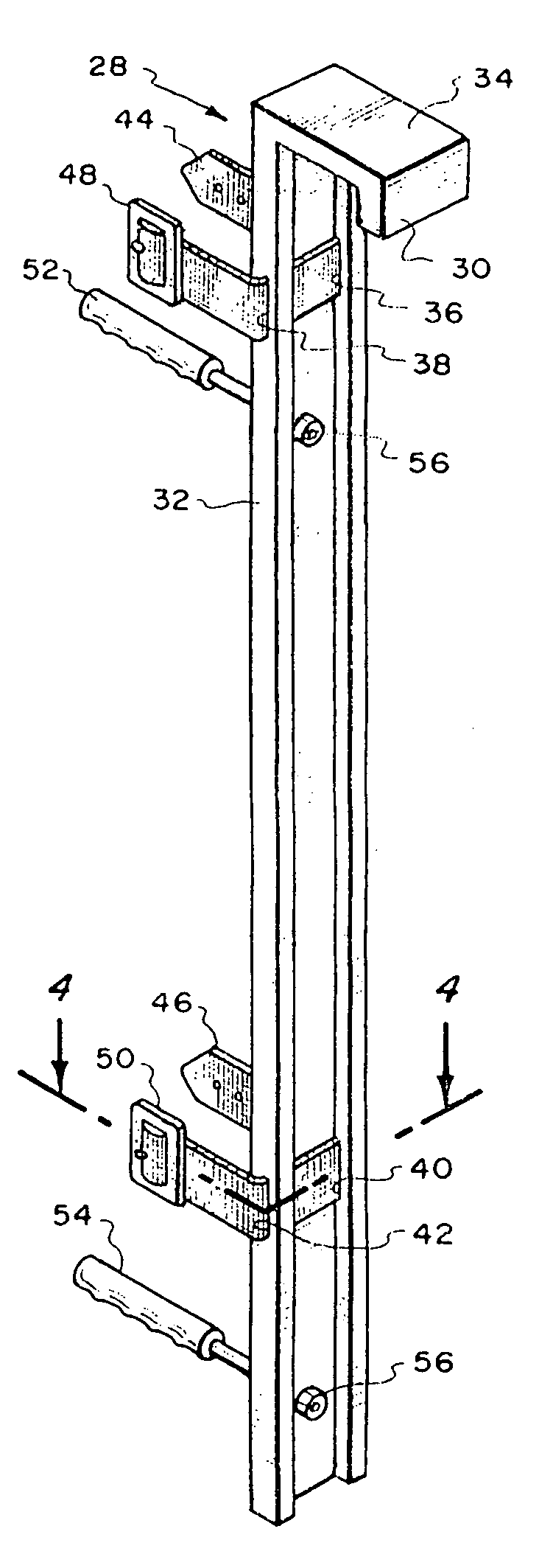
Method used


Image

  • Holder for a concrete slurry hose
  • Holder for a concrete slurry hose

Examples


Embodiment Construction

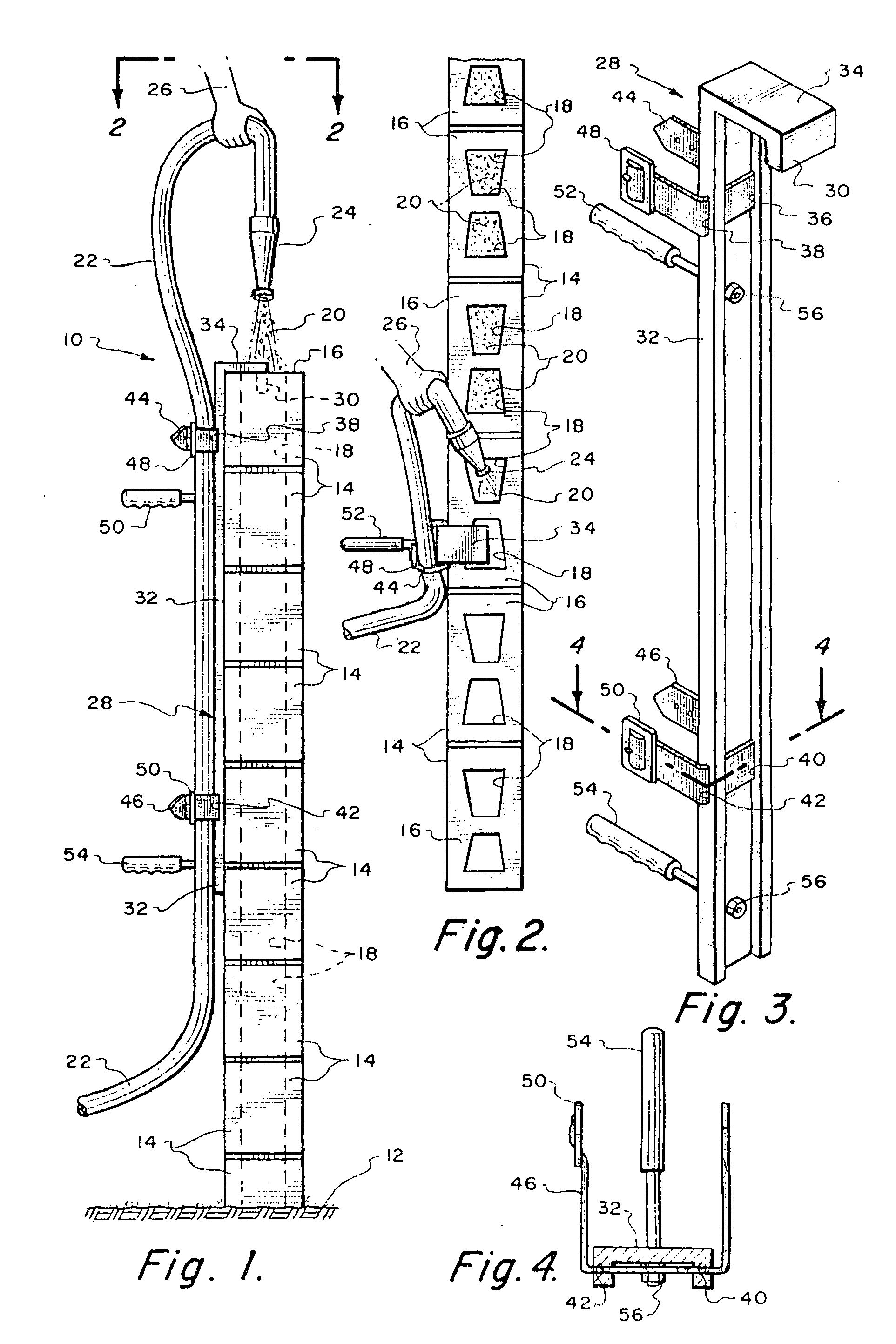
[0019]Referring particularly to the drawing, there is shown a conventional block wall 10 which is constructed on the ground 12. The block wall 10 defines a top edge 16. The block wall 10 is constructed of a plurality of identical cement or cinder blocks 14. Each block 14 has a pair of internal openings 18.

[0020]The openings 18 are to be filled with a cement sand slurry 20. This slurry 20 is to be supplied into each of the openings 18 from a source (not shown) through a rubber or other flexible material hose 22. Hose 22 terminates at its outer free end in a nozzle 24 through which the slurry 20 is to be dispensed through the opening. The hose 22 adjacent nozzle 24 is to be supported by a human such as depicted by the human hand 26.

[0021]The hose holder 28 of this invention is designed to remove the bulk of the weight that the user carries during the filling of the openings 18 with the slurry 20. Hose holder 28 of this invention is formed of an elongated channel-shaped body. This bod...


PUM


Abstract

A holder for a concrete slurry hose connectable to support a hose for dispensing a slurry at an elevated location such as at the top of a wall. The holder comprises an elongated body which is to be supported at the top of the wall. The body includes a pair of straps which would be secured to the hose some spaced distance from the dispensing end of the hose. The lower end of the body includes a pair of handles. These handles are to be grasped and used by a human to facilitate movement of the body to various locations along the wall.

Description

BACKGROUND OF THE INVENTION[0001]1. Field of the Invention[0002]The field of this invention relates to holders and more particularly to a holder for a hose which is designed to dispense a concrete slurry at an elevated location.[0003]2. Description of the Related Art[0004]The present invention is discussed in relation to a slurry. This slurry, though flowable, is not totally liquid. For example, it is common to mix water, cement and sand into a slurry and then pump that slurry through a hose to be dispensed at a desired location. This dispensing of slurry is exceedingly common in the construction industry. Although the present application is discussed in terms of dispensing a slurry, it is considered to be within the scope of this invention that this is to include any kind of a flowable medium.[0005]Within the construction industry, it is common to pump a cement slurry through a hose to be dispensed at a desired location. One of these desired locations is within a block wall. Block...

Claims


Application Information

Patent Timeline
Patent Type & Authority Patents(United States)
IPC IPC(8): E04G21/04
CPCE04G21/04E04G21/0418
Inventor AYALA, HENRY
Owner AYALA HENRY
Learn More