Controlled fusion in a field reversed configuration and direct energy conversion

a reversed configuration and fusion technology, applied in the field ofplasma physics, can solve the problems of low efficiency (less than 30%), high radioactivity, and damage to the structure of the reactor wall, and achieve the effects of reducing or eliminating anomalous ions transport, high efficiency, and facilitating controlled fusion

Inactive Publication Date: 2005-05-17
RGT UNIV OF CALIFORNIA +1
View PDF40 Cites 64 Cited by
  • Summary
  • Abstract
  • Description
  • Claims
  • Application Information

AI Technical Summary

Benefits of technology

[0019]The present invention is directed to a system that facilitates controlled fusion in a magnetic field having a field-reversed topology and the direct conversion of fusion product energies to electric power. The system, referred to herein as a plasma-electric power generation (PEG) system, preferably includes a fusion reactor having a containment system that tends to substantially reduce or eliminate anomalous transport of ions and electrons. In addition, the PEG system includes an energy conversion system coupled to the reactor that directly converts fusion product energies to electricity with high efficiency.

Problems solved by technology

The disadvantages of neutronic reactions are that (1) the flux of fast neutrons creates many problems, including structural damage of the reactor walls and high levels of radioactivity for most construction materials; and (2) the energy of fast neutrons is collected by converting their thermal energy to electric energy, which is very inefficient (less than 30%).
The advanced fuels have disadvantages, too.
Also, it is much more difficult to cause the advanced fuels to fuse.
Electrons, however, have a much smaller gyroradius, so they respond to the fluctuations and transport anomalously.
A Tokamak reactor using D-T fuel has the additional problem that most of the energy of the fusion products energy is carried by 14 MeV neutrons, which cause radiation damage and induce reactivity in almost all construction materials due to the neutron flux.
In addition, the conversion of their energy into electricity must be by a thermal process, which is not more than 30% efficient.
Producing useful fusion reactions in this type of reactor has been infeasible because the background plasma slows down the ion beams.
In none of these devices, however, does an equilibrium electric field play any part.
None of these patents consider electrostatic confinement of electrons and magnetic confinement of ions.
Although there have been many research projects on electrostatic confinement of ions, none of them have succeeded in establishing the required electrostatic fields when the ions have the required density for a fusion reactor.
Lastly, none of the patents cited above discuss a field reversed configuration magnetic topology.

Method used


Image

  • Controlled fusion in a field reversed configuration and direct energy conversion
  • Controlled fusion in a field reversed configuration and direct energy conversion
  • Controlled fusion in a field reversed configuration and direct energy conversion

Examples


Embodiment Construction

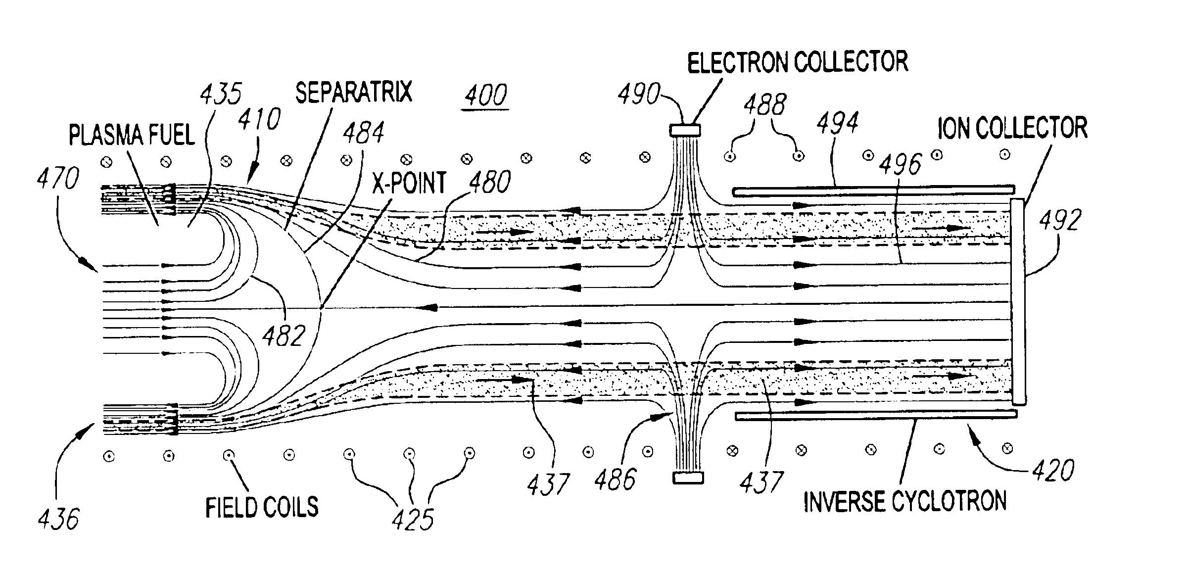
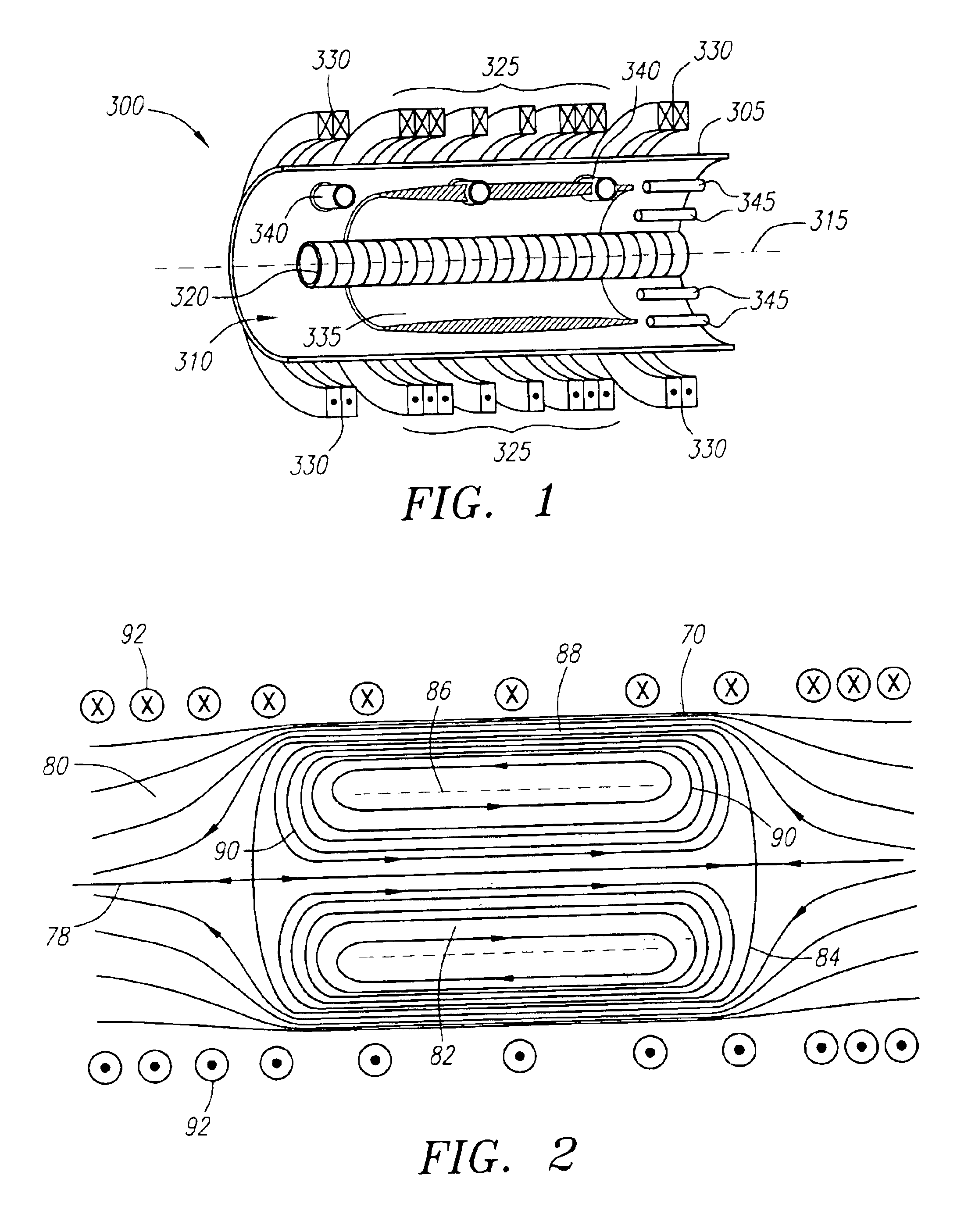
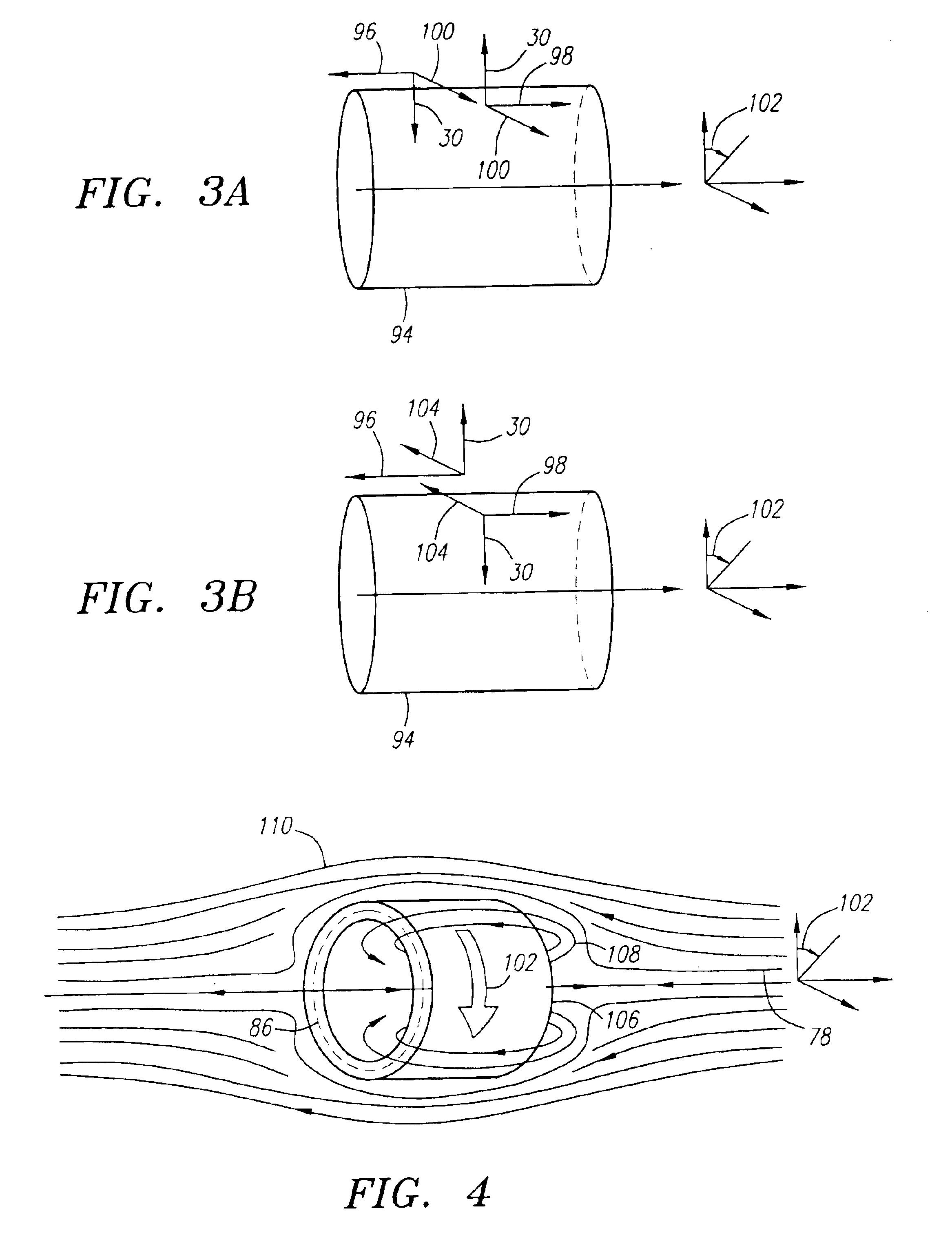
[0060]As illustrated in the figures, a plasma-electric power generation system of the present invention preferably includes a colliding beam fusion reactor coupled to a direct energy conversion system. As alluded to above, an ideal fusion reactor solves the problem of anomalous transport for both ions and electrons. The solution to the problem of anomalous transport found herein makes use of a containment system with a magnetic field having a field reversed configuration (FRC). The anomalous transport of ions is avoided by magnetic confinement in the FRC in such a way that the majority of the ions have large, non-adiabatic orbits, making them insensitive to short-wavelength fluctuations that cause anomalous transport of adiabatic ions. In particular, the existence of a region in the FRC where the magnetic field vanishes makes it possible to have a plasma comprising a majority of non-adiabatic ions. For electrons, the anomalous transport of energy is avoided by tuning the externally ...


PUM


Abstract

A system and apparatus for controlled fusion in a field reversed configuration (FRC) magnetic topology and conversion of fusion product energies directly to electric power. Preferably, plasma ions are magnetically confined in the FRC while plasma electrons are electrostatically confined in a deep energy well, created by tuning an externally applied magnetic field. In this configuration, ions and electrons may have adequate density and temperature so that upon collisions they are fused together by the nuclear force, thus forming fusion products that emerge in the form of an annular beam. Energy is removed from the fusion product ions as they spiral past electrodes of an inverse cyclotron converter. Advantageously, the fusion fuel plasmas that can be used with the present confinement and energy conversion system include advanced (aneutronic) fuels.

Description

CROSS-REFERENCE TO RELATED APPLICATIONS[0001]This application is a continuation of U.S. application Ser. No. 10 / 077,661, filed Feb. 14, 2002, now U.S. Pat. No. 6,628,740, which is a continuation-in-part of U.S. application Ser. No. 09 / 902,934, filed Jul. 10, 2001, now abandoned, which is a continuation of U.S. application Ser. No. 08 / 953,130, filed Oct. 17, 1997, now abandoned, and said application Ser. No. 10 / 077,661 is a continuation-in-part of U.S. application Ser. No. 09 / 915,965, filed Jul. 25, 2001, which is a continuation of U.S. application Ser. No. 09 / 878,046, filed Jun. 8, 2001, now abandoned, which is a continuation-in-part of U.S. application Ser. No. 08 / 953,130, filed Oct. 17, 1997, now abandoned, which applications are fully incorporated herein by reference, and said application Ser. No. 10 / 077,661 claims the benefit of provisional U.S. application Ser. No. 60 / 277,374, filed Mar. 19, 2001, and provisional U.S. application Ser. No. 60 / 297,086, filed on Jun. 8, 2001, whic...

Claims


Application Information

Patent Timeline
Patent Type & Authority Patents(United States)
IPC IPC(8): H05H1/02H05H1/12
CPCG21B1/052Y02E30/122Y02E30/10
Inventor MONKHORST, HENDRIK J.ROSTOKER, NORMAN
Owner RGT UNIV OF CALIFORNIA
Why Eureka
Try Eureka