Retrofocus, wide-angle lens

Inactive Publication Date: 2005-05-17
FUJI PHOTO OPTICAL CO LTD
View PDF8 Cites 13 Cited by
  • Summary
  • Abstract
  • Description
  • Claims
  • Application Information

AI Technical Summary

Benefits of technology

[0003]The present invention relates to a retrofocus, wide-angle lens with a long back focus that provides

Problems solved by technology

Although each of the above-mentioned retrofocus, wide-angle lenses provides an adequate back focal length, the correction of aberration is at large field angles—especially the correction of lateral color—is difficult due to the asymmetric construction about the stop

Method used


Image

  • Retrofocus, wide-angle lens
  • Retrofocus, wide-angle lens
  • Retrofocus, wide-angle lens

Examples


Example

Embodiment 1

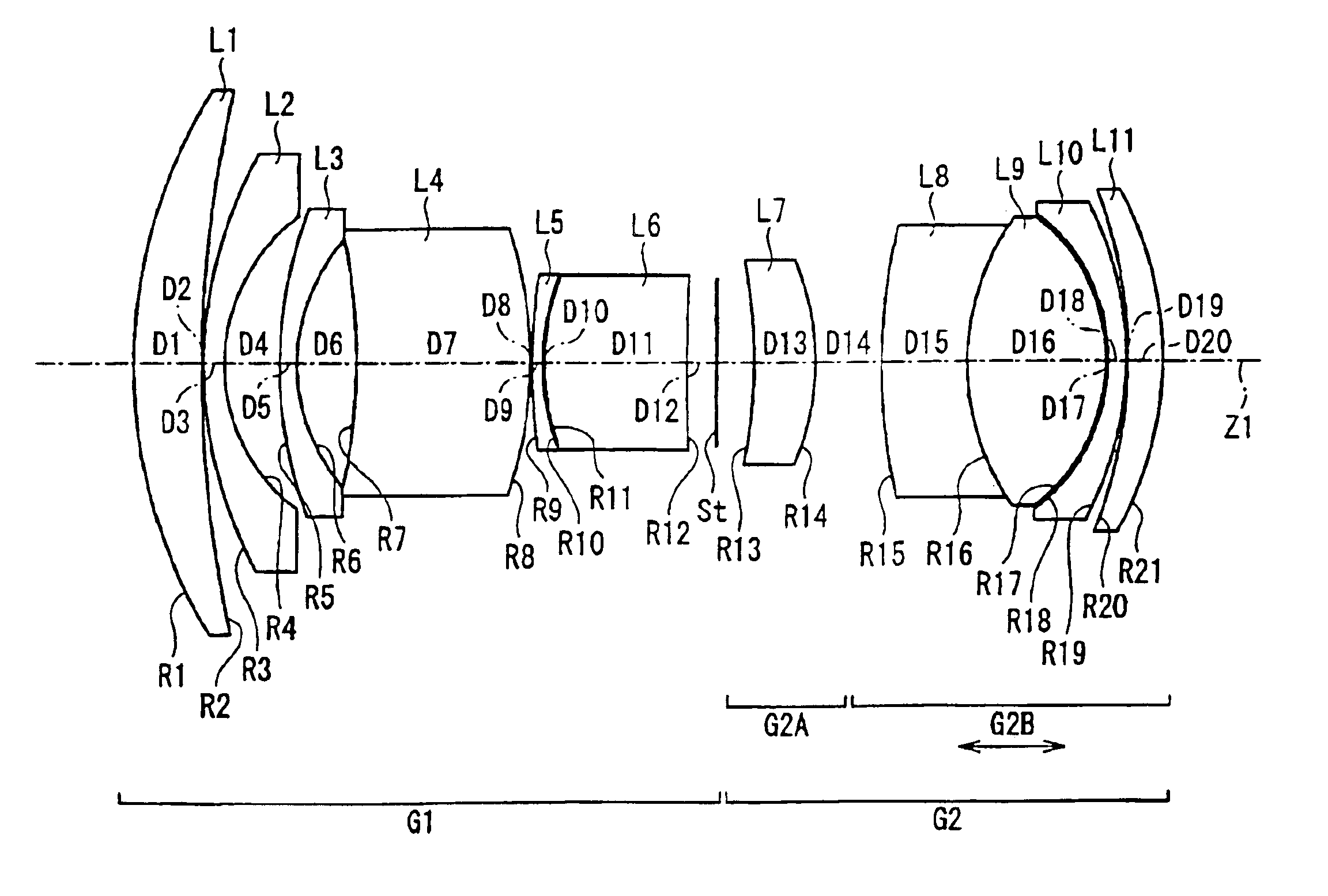
[0044]FIG. 1 shows the basic lens element configuration and lens group positions of the retrofocus, wide-angle lens of the present invention and specifically shows Embodiment 1.

[0045]Table 1 below lists the group identifier at the first object-side lens surface of the lens group, the surface number # in order from the object side, the radius of curvature R (in mm) of each surface, the on-axis surface spacing D (in mm), as well as the refractive index Nd and the Abbe number νd (both at the d-line) of each lens element for Embodiment 1. Listed in the middle portion of Table 1 are the focal length f, the f-number FNO, the maximum image angle 2ω, φ17, and the back focal length fB for Embodiment 1. Furthermore, listed in the bottom portion of Table 1 are the values corresponding to Conditions (1)-(10) for Embodiment 1.

[0046]TABLE 1Group#RDNdνdG1160.7738.081.7433049.22145.3410.15350.6352.441.8466623.8421.3626.71550.5842.041.8340037.3622.2247.087−71.42920.951.4874970.48−50.0340...

Example

Embodiment 2

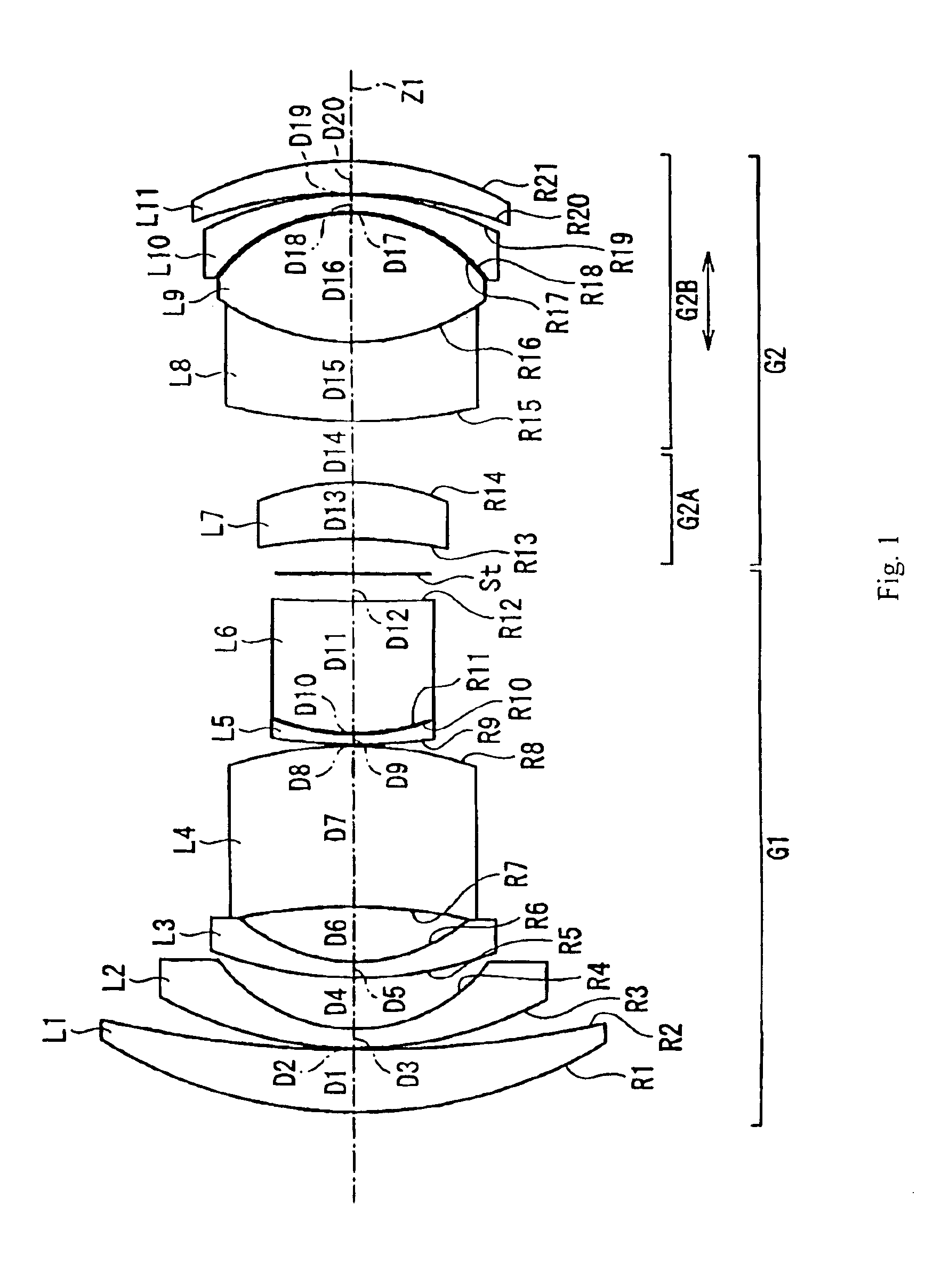
[0048]Embodiment 2, shown in FIG. 2, is very similar to Embodiment 1 and uses the same number of lens elements. Because Embodiment 2 is very similar to Embodiment 1, the differences between Embodiment 2 and Embodiment 1 will be evident from Table 2 that follows.

[0049]Table 2 below lists the group identifier at the first object-side lens surface of the lens group, the surface number # in order from the object side, the radius of curvature R (in mm) of each surface, the on-axis surface spacing D (in mm), as well as the refractive index Nd and the Abbe number νd (both at the d-line) of each lens element for Embodiment 2. Listed in the middle portion of Table 2 are the focal length f, the f-number FNO, the maximum image angle 2ω, φ17, and the back focal length fB for Embodiment 2. Furthermore, listed in the bottom portion of Table 2 are the values corresponding to Conditions (1)-(10) for Embodiment 2.

[0050]TABLE 2Group#RDNdνdG1160.4848.051.7433049.22141.9740.14347.2662.421.8...

Example

Embodiment 3

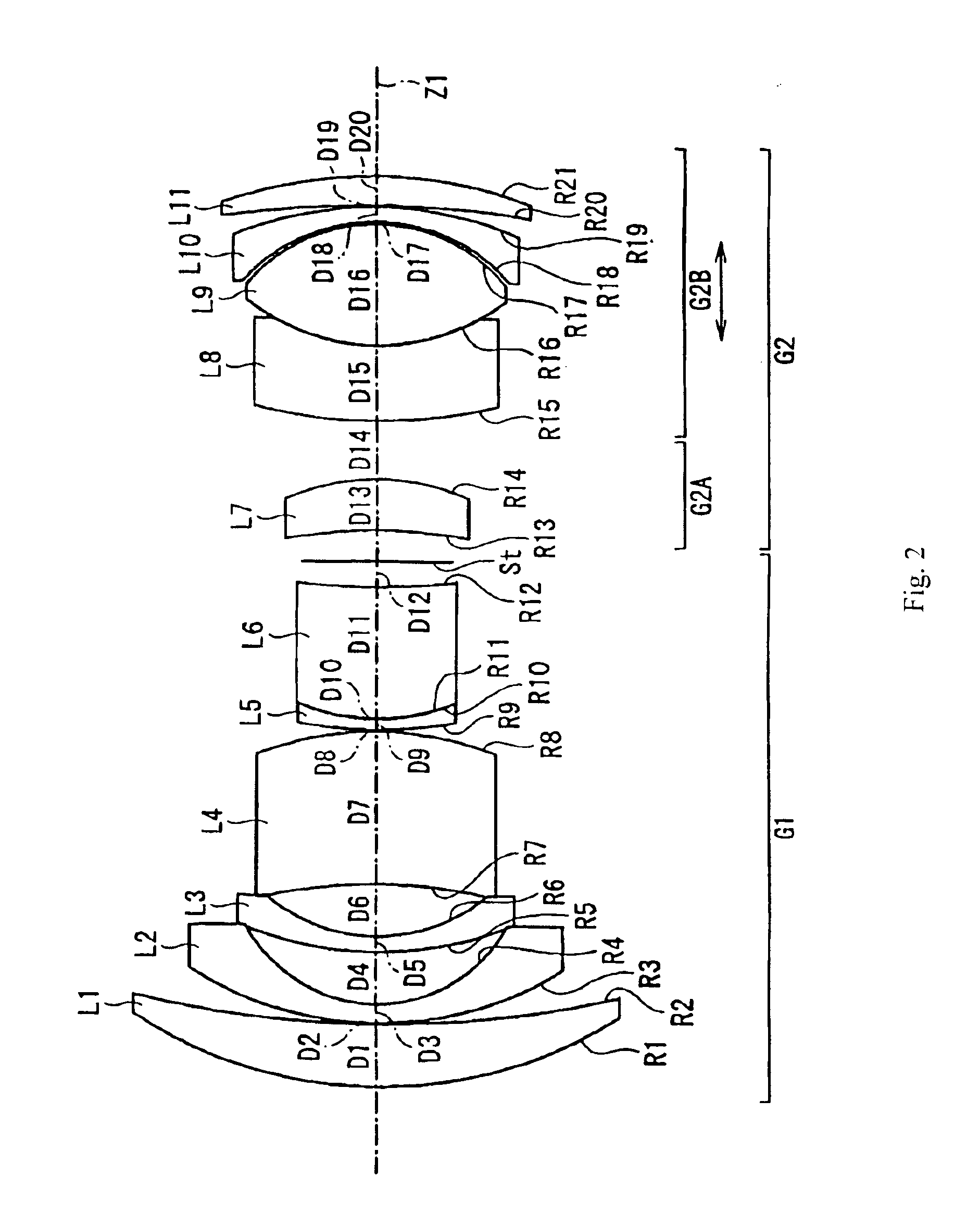
[0052]Embodiment 3, shown in FIG. 3, is very similar to Embodiment 1 and uses the same number of lens elements. Because Embodiment 3 is very similar to Embodiment 1, the differences between Embodiment 3 and Embodiment 1 will be evident from Table 3 that follows.

[0053]Table 3 below lists the group identifier at the first object-side lens surface of the lens group, the surface number # in order from the object side, the radius of curvature R (in mm) of each surface, the on-axis surface spacing D (in mm), as well as the refractive index Nd and the Abbe number νd (both at the d-line) of each lens element for Embodiment 3. Listed in the middle portion of Table 3 are the focal length f, the f-number FNO, the maximum image angle 2ω, φ17, and the back focal length fB for Embodiment 3. Furthermore, listed in the bottom portion of Table 3 are the values corresponding to Conditions (1)-(10) for Embodiment 3.

[0054]TABLE 3Group#RDNdνdG1162.0058.851.7433049.22148.9370.15353.6382.661.8...


PUM


Abstract

A retrofocus, wide-angle lens includes a first lens group of negative refractive power, a stop, and a second lens group of positive refractive power. The first lens group includes, in order from the object side, a meniscus lens elements having positive refractive power, two meniscus lens elements having negative refractive power, and a thick lens element. The second lens group includes a cemented lens component that includes a lens element having negative refractive power and a biconvex lens element that is on the object side of a meniscus lens element having negative refractive power with its concave surface on the object side. The second lens group may include a meniscus lens component having positive refractive power on the object side of the biconvex lens element and a meniscus lens component having positive refractive power on the image side of the meniscus lens element having negative refractive power.

Description

BACKGROUND OF THE INVENTION[0001]Generally, in a wide-angle lens for a single lens reflex camera, a retrofocus lens construction has been used that includes a lens group having negative refractive power and a lens group having positive refractive power arranged in that order from the object side. The lens groups define an asymmetric arrangement about a stop used as an aperture stop in order to provide a desirably long back focal length of the retrofocus, wide-angle lens. Examples of such retrofocus, wide angle lenses are described in Japanese Laid-Open Patent Application 2002-214526 and Japanese Laid-Open Patent Application H07-261076.[0002]Although each of the above-mentioned retrofocus, wide-angle lenses provides an adequate back focal length, the correction of aberration is at large field angles—especially the correction of lateral color—is difficult due to the asymmetric construction about the stop. Because digital cameras use detectors having light receiving characteristics tha...

Claims


Application Information

Patent Timeline
IPC IPC(8): G02B13/04
CPCG02B13/04
Inventor SUZUKI, TAKASHI
Owner FUJI PHOTO OPTICAL CO LTD
Why Eureka
Try Eureka