Image scanning lens and image scanning device that uses same

a scanning lens and image technology, applied in the field of image scanning lenses and image scanning devices, can solve the problems of insufficient lateral color correction in order to enable desired color image reading, insufficient miniaturization, and insufficient image scanning lenses having desirable image magnification, etc., to achieve excellent lateral color correction, wide field of view, and low cost

Inactive Publication Date: 2006-02-14
FUJI PHOTO OPTICAL CO LTD
View PDF6 Cites 8 Cited by
  • Summary
  • Abstract
  • Description
  • Claims
  • Application Information

AI Technical Summary

Benefits of technology

[0007]The present invention relates to an image scanning lens, and an image scanning device, such as a facsimile device or an image scanner, that uses it that provides excellent correction of chromatic aberration for reading color images, achieves a wide field of view, can be miniaturized, and can be produced at low cost.

Problems solved by technology

However, recently, high resolution has become an urgent need in image scanning devices, such as facsimile machines and image scanners, tending to sharply increase the number of pixels needed in the image pickup devices.
As the number of pixels is increased, the size of the image pickup element becomes larger, making it difficult to obtain an image scanning lens having desirable image magnification, a wide field of view, and sufficient miniaturization.
However, the half-field angles of the image scanning lenses described in the above mentioned Japanese Laid-Open Patent Application H09-127414 are relatively narrow, 18 to 20 degrees, which does not respond to the need for a wide angle of view.
On the other hand, the half-field angles of the image scanning lenses described in Japanese Laid-Open Patent Application H05-264900 are relatively wide at about 23.5 degrees, but they are not necessarily sufficient in terms of the correction of lateral color to enable desired reading of color images.

Method used


Image

  • Image scanning lens and image scanning device that uses same
  • Image scanning lens and image scanning device that uses same
  • Image scanning lens and image scanning device that uses same

Examples


embodiment 1

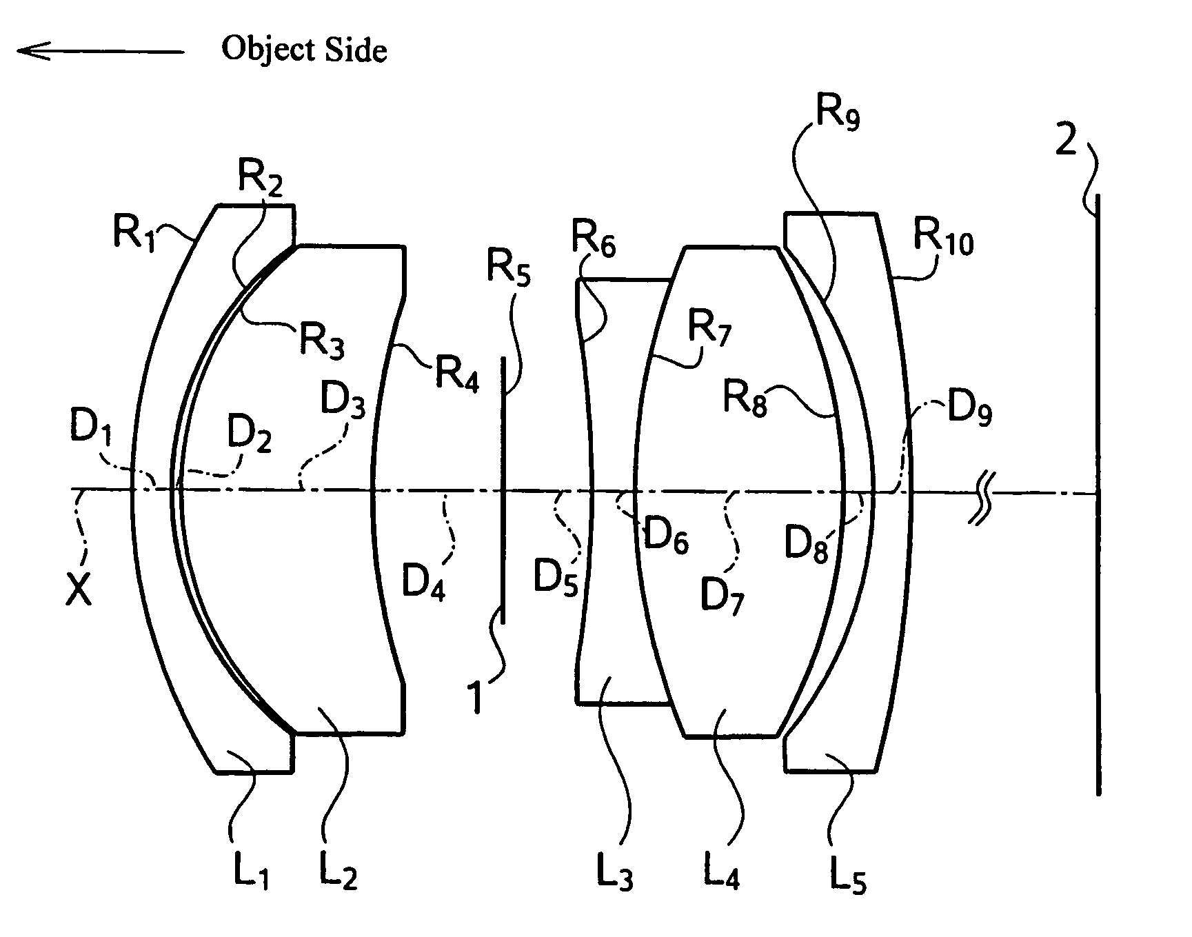
[0045]FIG. 1 shows the basic lens element configuration of the image scanning lens of Embodiment 1.

[0046]Table 1 below lists the surface number # in order from the object side, the radius of curvature R (in mm) of each surface, the on-axis surface spacing D (in mm), the refractive index Nd (at the d-line), the refractive index Ng (at the g-line), the refractive index NF (at the F-line), the refractive index NC (at the C-line), the Abbe number νd (at the d-line), and the product name that the manufacturer (O'Hara) uses to identify the optical material used to make each lens element for Embodiment 1. Listed in the middle portion of Table 1 are the focal length f, the f-number FNO, the magnification β, and the maximum field angle 2ω for Embodiment 1. Furthermore, listed in the bottom portion of Table 1 are the values corresponding to Conditions (1)–(5) for Embodiment 1.

[0047]

TABLE 1#RDNdNgNFNCνdOptical Material125.841.971.654121.675171.665711.6492339.7S-NBH5215.450.45315.749.471.618001...

embodiment 2

[0050]Embodiment 2 is very similar to Embodiment 1 and uses the same number of lens elements. Because Embodiment 2 is very similar to Embodiment 1, the differences between Embodiment 2 and Embodiment 1 will be evident from Table 2 that follows.

[0051]Table 2 below lists the surface number # in order from the object side, the radius of curvature R (in mm) of each surface, the on-axis surface spacing D (in mm), the refractive index Nd (at the d-line), the refractive index Ng (at the g-line), the refractive index NF (at the F-line), the refractive index NC (at the C-line), the Abbe number νd (at the d-line), and the product name that the manufacturer (O'Hara) uses to identify the optical material used to make each lens element for Embodiment 2. Listed in the middle portion of Table 2 are the focal length f, the f-number FNO, the magnification β, and the maximum field angle 2ω for Embodiment 2. Furthermore, listed in the bottom portion of Table 2 are the values corresponding to Condition...

embodiment 3

[0055]Embodiment 3 is very similar to Embodiment 1 and uses the same number of lens elements. Because Embodiment 3 is very similar to Embodiment 1, the differences between Embodiment 3 and Embodiment 1 will be evident from Table 3 that follows.

[0056]Table 3 below lists the surface number # in order from the object side, the radius of curvature R (in mm) of each surface, the on-axis surface spacing D (in mm), the refractive index Nd (at the d-line), the refractive index Ng (at the g-line), the refractive index NF (at the F-line), the refractive index NC (at the C-line), the Abbe number νd (at the d-line), and the product name that the manufacturer (O'Hara) uses to identify the optical material used to make each lens element for Embodiment 3. Listed in the middle portion of Table 3 are the focal length f, the f-number FNO, the magnification β, and the maximum field angle 2ω for Embodiment 3. Furthermore, listed in the bottom portion of Table 3 are the values corresponding to Condition...


PUM


Abstract

An image scanning lens includes four lens components that may include five lens elements as follows: a first lens element having negative refractive power and a meniscus shape with its convex surface on the object side, a second lens element having positive refractive power and a meniscus shape with its convex surface on the object side, a stop, a third biconcave lens element cemented to a fourth biconvex lens element, and a fifth lens element having negative refractive power and a meniscus shape with its concave surface on the object side. The image scanning lens satisfies certain conditions related to the focal lengths of the first, second, and third lens components of the image scanning lens and to the anomalous dispersion of the second lens element. An image scanning device, such as an image scanner, with an image pickup device, such as a CCD, uses the image scanning lens.

Description

FIELD OF THE INVENTION[0001]The present invention relates to an image scanning lens and an image scanning device for reading an image on a manuscript, such as a facsimile machine or an image scanner, and particularly relates to an image scanning lens with a four-component, five-element construction that is suitable for use in reading a color image as part of an image reading device.BACKGROUND OF THE INVENTION[0002]Image scanning devices in which an image on a manuscript is formed on an image pickup device, such as a CCD, via an optical system in order to convey the image information are known. Recently, miniaturization and low cost have been required in such image scanning devices, especially in image scanners and similar devices, in turn making low cost and miniaturization of the image scanning lens highly desirable.[0003]Various types of image scanning lenses used in image scanning devices, such as facsimile machines and image scanners, are known. For example, Japanese Laid-Open P...

Claims


Application Information

Patent Timeline
Patent Type & Authority Patents(United States)
IPC IPC(8): G02B15/14G02B9/34G02B13/24
CPCG02B13/24G02B9/34
Inventor YAMAMOTO, YOKOYAMAKAWA, HIROMITSU
Owner FUJI PHOTO OPTICAL CO LTD
Why Eureka
Try Eureka