Imaging lens system

a technology of imaging lens and lens body, which is applied in the field of imaging lens system, can solve the problems of insufficiently meeting the high picture quality and high resolution which are required for imaging lens system in these days, and conventional lens system is not yet sufficient to achieve the demands of high optical, size and weight, and achieve excellent optical performance, excellent distortion correction, and reduced incident angle

Inactive Publication Date: 2007-03-27
ENPLAS CORP
View PDF6 Cites 8 Cited by
  • Summary
  • Abstract
  • Description
  • Claims
  • Application Information

AI Technical Summary

Benefits of technology

[0013]With the imaging lens system, by the combination of the first lens, the second lens and the third lens, it becomes possible to achieve reduction of the size and weight while achieving an excellent correction of various aberrations such as the chromatic aberration, distortion, curvature of field and the like. Also, it enables to maintain the appropriate back focus and, at the same time, maintain the telecentricity by reducing the angle of incident of the incoming main light ray against a sensor surface of an image-taking element.
[0050]As described, the imaging lens system of the present invention is an imaging les system with an excellent optical performance in which the distortion is more excellently corrected. Further, the telecentricity can be more excellently maintained.

Problems solved by technology

Such CCD camera needs to be mounted on a limited space.
However, although these types are extremely advantageous in terms of reducing the size and weight of the lens system, they cannot sufficiently meet the high picture quality and high resolution which are required for the imaging lens system in these days.
However, the conventional lens system is not yet sufficient to achieve the demands for high optical performance such as a high picture quality and high resolution through well-correcting chromatic aberration and, at the same time, to achieve further reduction of the size and weight (shortening the whole length) of the lens system itself.
Thus, it is difficult to shorten the whole length of the lens system while sufficiently maintaining a high telecentricity.

Method used


Image

  • Imaging lens system
  • Imaging lens system
  • Imaging lens system

Examples


examples

[0110]Next, EXAMPLES of the present invention will be described by referring to FIG. 2 to FIG. 19.

[0111]In the Examples, F NO denotes F number, ω denotes a half angle of view, and r denotes the radius of center curvature. Further, d denotes the distance to the next optical surface, nd denotes the index of refraction against the d line (yellow) and νd denotes the Abbe number (d line being the reference).

[0112]k, A, B, C and D denote each coefficient in a following expression (8). In other words, the shape of the aspherical surface is expressed by the following expression provided that the optical axial direction is taken as the Z axis, the direction orthogonal to the optical axis is the X axis, the forwarding direction of light is positive, k is the constant of cone, A, B, C, D are the aspherical coefficients, and r is the radius of center curvature:

Z(X)=r−1X2 / [1+{1−(k+1)r−2X2}1 / 2]+AX4+BX6+CX8+DX10  (8)

first example

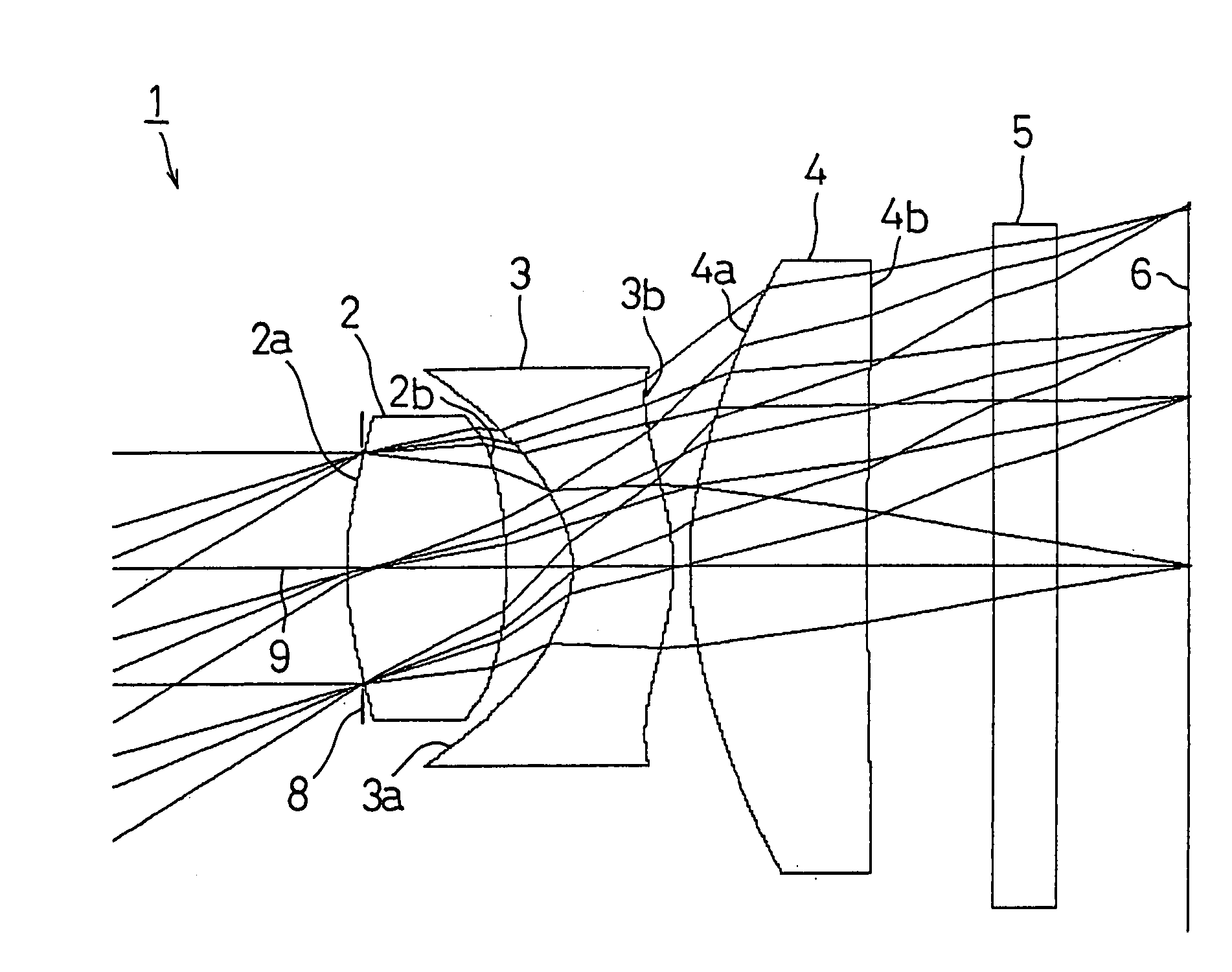
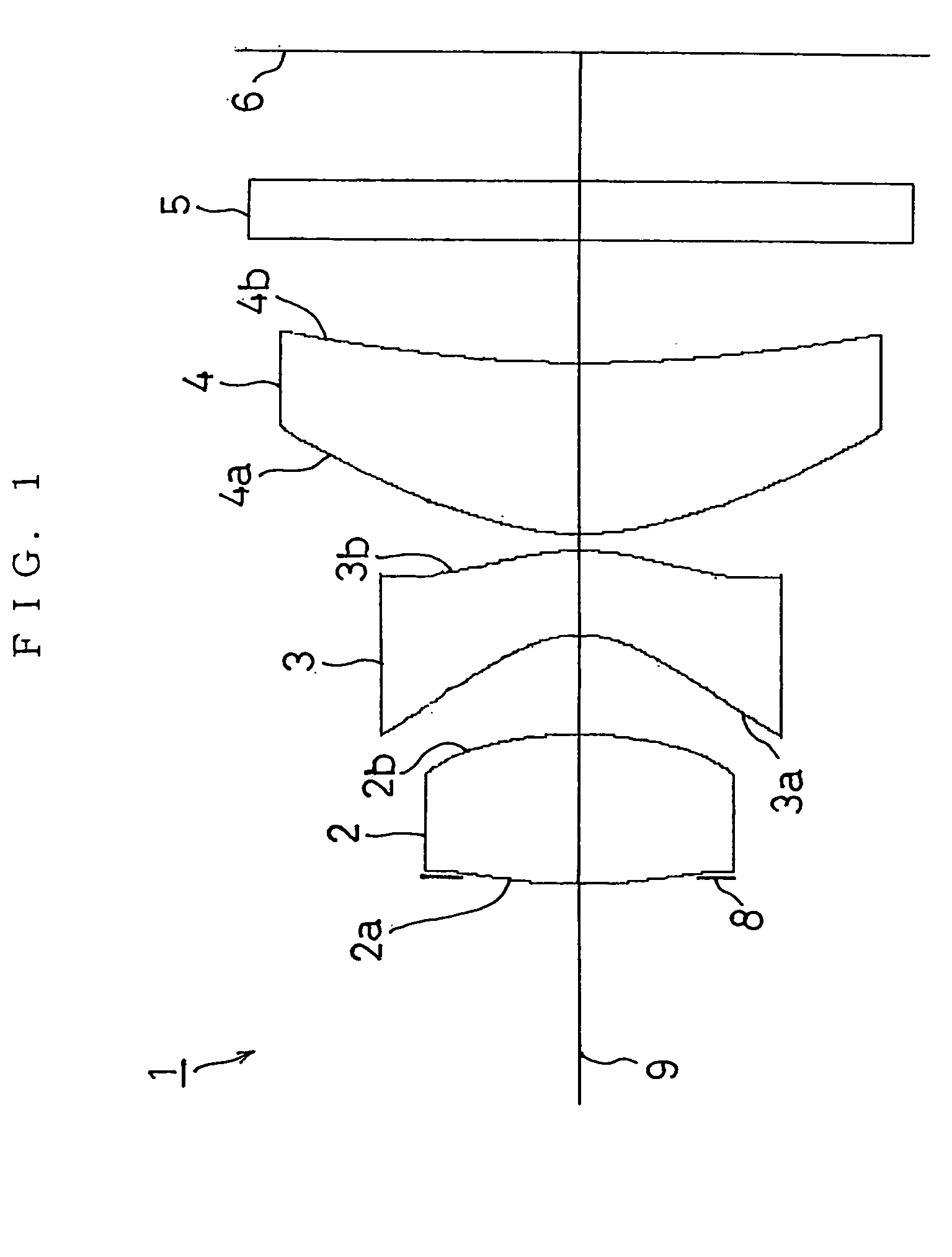
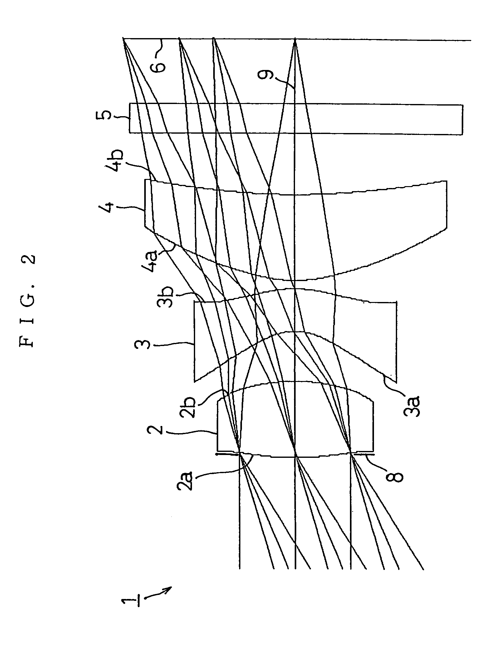
[0113]FIG. 2 shows FIRST EXAMPLE of the present invention. In FIRST EXAMPLE, a diaphragm 8 was disposed on the first face 2a side of the first lens 2 in the same manner as the one shown in FIG. 1. In FIRST EXAMPLE, the diaphragm 8 was regarded as the same surface as the first face 2a of the first lens 2. The first to third lenses were formed using a resin material, respectively.

[0114]An imaging lens system 1 of FIRST EXAMPLE was set under the following condition.

[0115]f=4.75 mm, F NO=2.8, ω=29°, f1=3.4965 mm

[0116]

Face Numberrdndνd(Object Point)∞1(First Face of First Lens)(Diaphragm)3.7041.251.525562(Second Face of First Lens)−3.2120.813(First Face of Second Lens)−0.8130.701.584304(Second Face of Second Lens)−1.8440.135(First Face of Third Lens)2.0241.421.525566(Second Face of Third Lens)9.5881.007(First Face of Cover Glass)0.00.501.517648(Second Face of Cover Glass)0.0(Image Surface)

[0117]

Face No.kABCD1−21.4192 0.27241073e−01−0.33111515e−010.00000000e+000.00000000e+0020.6432−0.38977...

second example

[0121]FIG. 5 shows SECOND EXAMPLE of the present invention. In SECOND EXAMPLE, the diaphragm 8 was disposed on the first face 2a side of the first lens 2 in the same manner as the one shown in FIG. 1. In SECOND EXAMPLE, the diaphragm 8 was regarded as the same surface as the first face 2a of the first lens 2. The first to third lenses were formed using a resin material, respectively.

[0122]The imaging lens system 1 of SECOND EXAMPLE was set under the following condition.

[0123]f=4.75 mm, F NO=2.8, ω=29°, f1=4.2889 mm

[0124]

Face Numberrdndνd(Object Point)∞1(First Face of First Lens)(Diaphragm)2.2501.101.525562(Second Face of First Lens)∞0.813(First Face of Second Lens)−1.0130.701.585304(Second Face of Second Lens)−1.7060.205(First Face of Third Lens)2.5641.431.525566(Second Face of Third Lens)7.3041.007(First Face of Cover Glass)0.00.501.517648(Second Face of Cover Glass)0.0(Image Surface))

[0125]

Face No.kABCD11.4480−0.10866073e−01−0.11267031e−01 0.00000000e+000.00000000e+0020.0000 0.175...


PUM


Abstract

An imaging lens system including a first lens having a main positive power whose convex surface faces an object side, a second lens in a meniscus shape having a negative power whose convex surface faces an image surface side, and a third lens having a positive power whose convex surface faces the object side. The three lenses are disposed in order from the object side to the image surface side.

Description

BACKGROUND OF THE INVENTION[0001]1. Field of the Invention[0002]The present invention relates to an imaging lens system and particularly, to an imaging lens system comprising three lenses which can be preferably reduced in size and weight to be used for an image-taking device utilizing an image sensor element such as a CCD, a CMOS or the like to be mounted on a portable computer, a visual telephone, a cellular phone, a digital camera and the like.[0003]2. Description of the Related Art[0004]Recently, there has been a remarkable development in the multimedia industry, and there has been an increasing demand for a camera utilizing an image sensor element such as a CCD, a CMOS or the like to be mounted on a portable computer, a visual telephone, a cellular phone, a digital camera and the like. Such CCD camera needs to be mounted on a limited space. Thus, it is desirable that the camera be small in size and light in weight.[0005]Accordingly, an imaging lens system used for such CCD came...

Claims


Application Information

Patent Timeline
Patent Type & Authority Patents(United States)
IPC IPC(8): G02B15/14G02B13/18G02B3/02G02B9/16G02B13/00
CPCG02B9/16G02B13/22G02B13/0035G02B13/18
Inventor NAKAMURA, AKIRA
Owner ENPLAS CORP
Why Eureka
Try Eureka