

Imaging optical system
- Summary
- Abstract
- Description
- Claims
- Application Information
AI Technical Summary
Benefits of technology
Problems solved by technology
Method used
Image

Examples
numerical embodiment 1
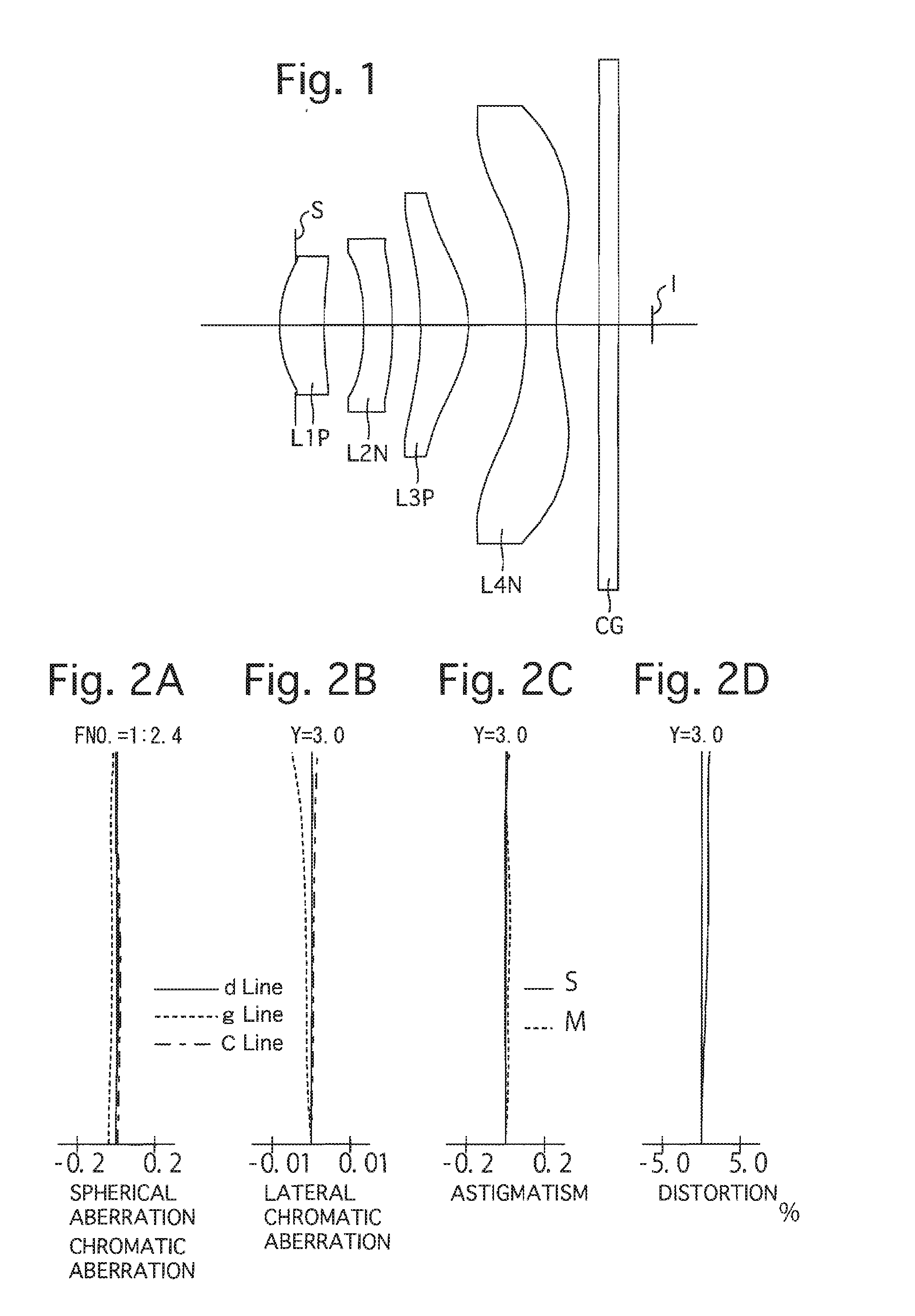
[0079]FIGS. 1 through 2D and Tables 1 through 3 show a first numerical embodiment of the imaging optical system. FIG. 1 shows a lens arrangement of the first numerical embodiment of the imaging optical system. FIGS. 2A, 2B, 2C and 2D show various aberrations that occurred in the lens arrangement shown in FIG. 1. Table 1 shows the lens surface data, Table 2 shows various data of the imaging optical system, and Table 3 shows aspherical surface data.
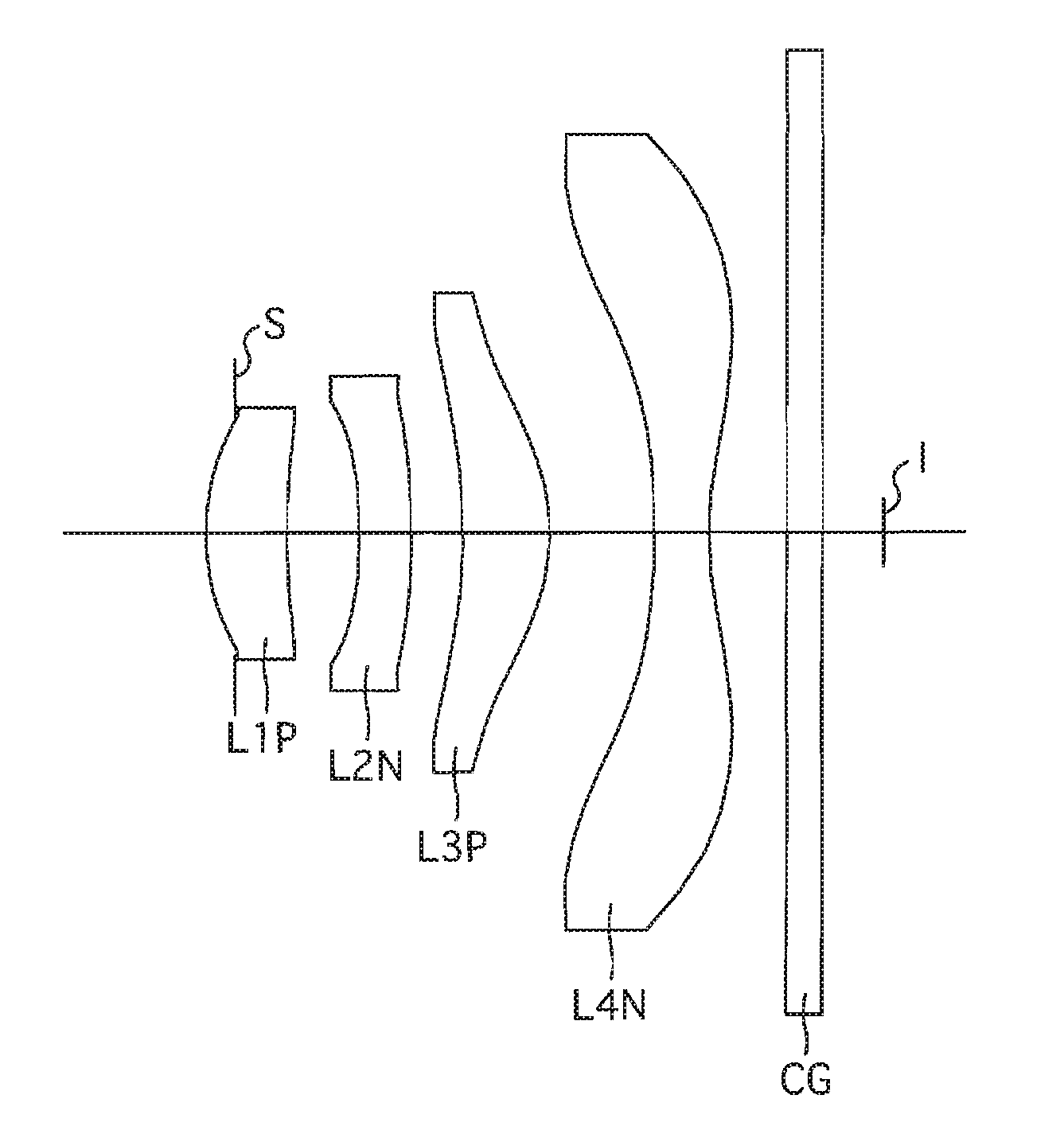
[0080]The imaging optical system of the first numerical embodiment is configured of a positive first lens element L1P, a negative second lens element L2N, a positive third lens element L3P, and a negative fourth lens element L4N, in that order from the object side.
[0081]The positive first lens element L1P has a meniscus profile having a convex surface on the object side, at the vicinity of the optical axis.
[0082]The negative second lens element L2N has a meniscus profile having a concave surface on the object side, at the vicinity of the op...
numerical embodiment 2
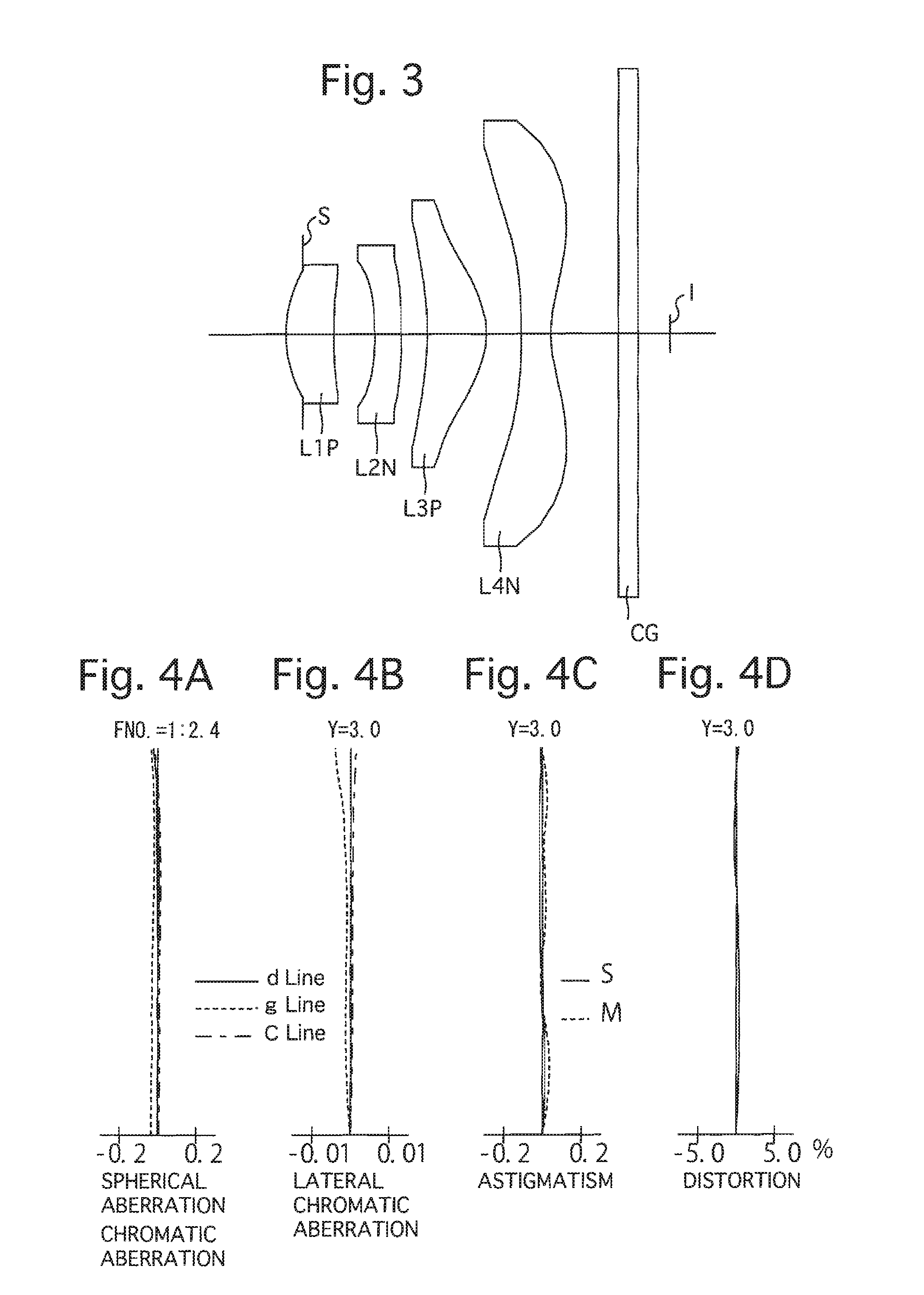
[0092]FIGS. 3 through 4D and Tables 4 through 6 show a second numerical embodiment of the imaging optical system. FIG. 3 shows a lens arrangement of the second numerical embodiment of the imaging optical system. FIGS. 4A, 4B, 4C and 4D show various aberrations that occurred in the lens arrangement shown in FIG. 3. Table 4 shows the lens surface data, Table 5 shows various data of the imaging optical system, and Table 6 shows aspherical surface data.
[0093]The fundamental lens arrangement of the second numerical embodiment is the same as that of the first numerical embodiment.
TABLE 4LENS SURFACE DATASurf. No.RDN dν d(Diaphragm) ∞−0.18711.4070.5181.5533271.724.0820.4503−3.6880.2901.6425022.54−9.9110.2875−3.4440.6471.5435855.76−0.8810.3847−7.7670.3201.5435855.781.2840.7349∞0.2101.5168064.210∞0.330
TABLE 5IMAGING OPTICAL SYSTEM DATAFocal length of imaging optical system [mm]:3.40f-number2.4Angle of view [deg.]:41.3Maximum image height [mm]:3.00
TABLE 6ASPHERICAL SURFACE DATASurf. No.KA4A6A...
numerical embodiment 3
[0094]FIGS. 5 through 6D and Tables 7 through 9 show a third numerical embodiment of the imaging optical system. FIG. 5 shows a lens arrangement of the third numerical embodiment of the imaging optical system. FIGS. 6A, 6B, 6C and 6D show various aberrations that occurred in the lens arrangement shown in FIG. 5. Table 7 shows the lens surface data, Table 8 shows various data of the imaging optical system, and Table 9 shows aspherical surface data.
[0095]The fundamental lens arrangement of the third numerical embodiment is the same as those of the first and second numerical embodiments.
TABLE 7LENS SURFACE DATASurf. No.RDN dν d(Diaphragm) ∞−0.18711.3280.5291.4971081.625.3820.4443−3.6610.290 1.64250 22.54−9.1980.2615−3.6440.584 1.5435855.76−1.0200.5967−3.9560.320 1.5435855.781.5490.3979∞0.210 1.51680 64.210∞0.342
TABLE 8IMAGING OPTICAL SYSTEM DATAFocal length of imaging optical system [mm]:3.33f-number2.4Angle of view [deg.]:42.0Maximum image height [mm]:3.00
TABLE 9ASPHERICAL SURFACE DAT...
PUM
 Abstract
Description
Claims
Application Information