Laptop computer base

a laptop computer and computer technology, applied in the field of laptop computer bases, can solve the problems of general discomfort, difficulty in maintaining the leg position, and difficulty in using the computer on the user's lap, and achieve the effect of inhibiting slippag

Inactive Publication Date: 2005-05-17
MICRON TECH INC
View PDF64 Cites 23 Cited by
  • Summary
  • Abstract
  • Description
  • Claims
  • Application Information

AI Technical Summary

Benefits of technology

[0007]The depressions in the lower surface may have several configurations. For example, in one embodiment, the depressions diverge apart from one another as they extend from the forward edge to the rear edge. In another embodiment, the depressions converge toward one another as they extend from the forward edge to the rear edge. The depressions may be shaped to engage both the upper and side surfaces of the user's legs, and the surface in the cavities of the depressions may have a rough texture, skid-resistant materials, or compressible materials to inhibit slippage between the user's legs and the base.

Problems solved by technology

One drawback with such a conventional laptop computer base is that it may be uncomfortable to use.
Furthermore, it may be difficult or awkward to support the computer on the user's lap.
Such a leg position is generally uncomfortable and difficult to maintain for long periods of time.
Thus, users are likely to shift either the computer or their legs in a manner that disrupts operation of the computer or increases the likelihood that the computer may fall from their laps.
Another drawback with the conventional laptop base is that it is difficult to balance the base on the user's legs.
For example, because the laptop base generally contacts only a small portion of the user's legs, the laptop computer may be easily dislodged from the user's lap.
Furthermore, because the base is typically made from a hard, smooth plastic, the laptop computer may slide off the user's lap, and damage the computer and / or data stored on the computer.
Such a conventional laptop computer may be particularly likely to slide from the user's lap when it is used in airplanes, buses or other cramped and crowded environments where the computer and / or the user may be jostled.

Method used


Image

  • Laptop computer base
  • Laptop computer base
  • Laptop computer base

Examples


Embodiment Construction

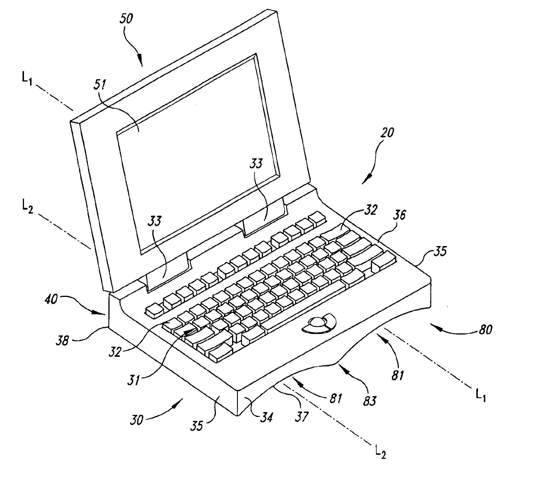
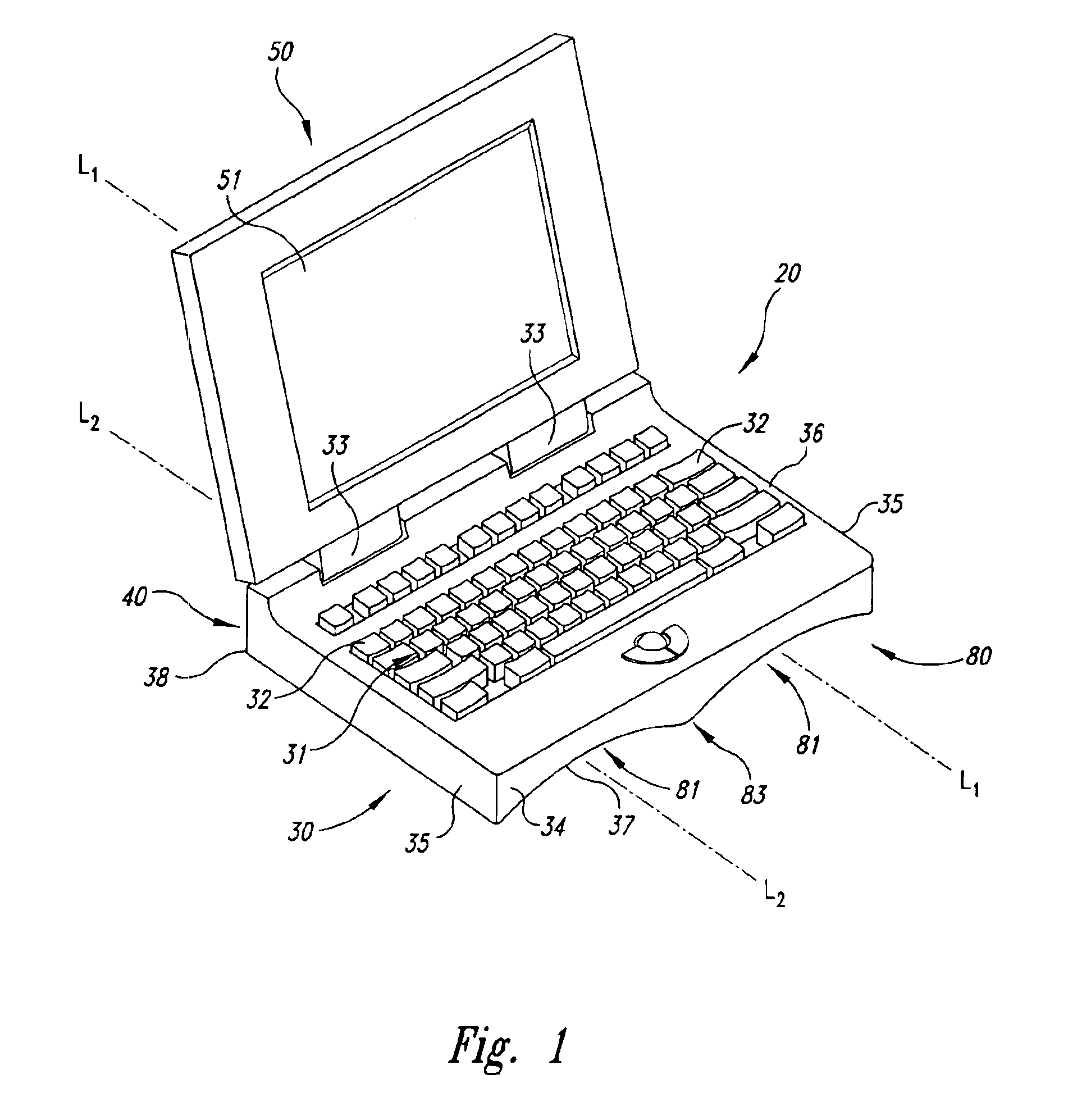
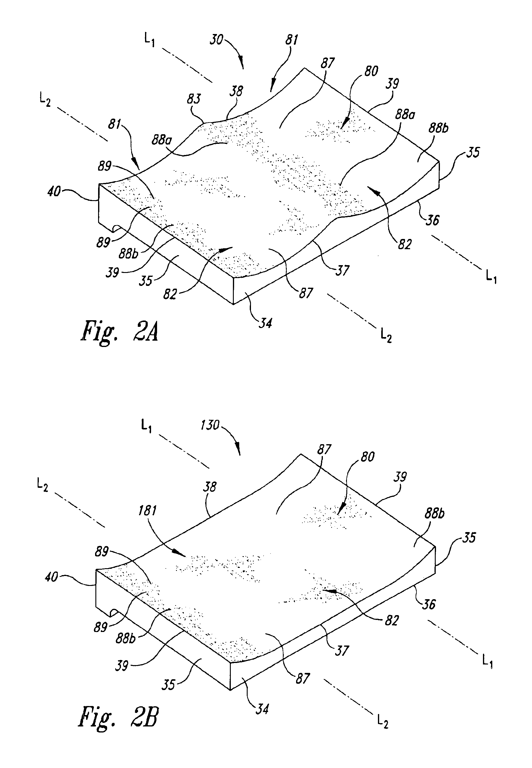
[0023]The present invention is directed toward bases for laptop computers. In one embodiment, the base may have a contoured lower surface to fit comfortably on a user's lap. In another embodiment, the base may have movable support members that allow users to position their legs in ergonomic sitting positions while still supporting the laptop computer. Many specific details of certain embodiments of the invention are set forth in the following description and in FIGS. 1-11 to provide a thorough understanding of such embodiments. One skilled in the art, however, will understand that the present invention may have additional embodiments and may be practiced without several of the details described in the following description.

[0024]FIG. 1 is a top isometric view of a laptop computer 20 having a base 30 coupled to a display housing 50 by a plurality of hinges 33. The base 30 may include a primary input device, such as a conventional keyboard 31 having a plurality of input keys 32, and t...


PUM


Abstract

A base for a laptop computer. In one embodiment, the base has an upper surface with a keyboard and a lower surface opposite the upper surface. The lower surface may have two depressions extending from a forward edge to a rear edge of the lower surface. The depressions are configured to engage both the upper and side surfaces of the user's legs in a manner that restricts relative motion between the base and the user's legs. In one embodiment, the depressions may have a rough texture and / or a skid-resistant material to further restrict motion of the base relative to the user's legs. In another embodiment, first and second support members may be movably attached to the base to move from a stowed position to an unstowed position for providing more surface area to engage the user's legs.

Description

CROSS-REFERENCE TO RELATED APPLICATIONS[0001]This application is a divisional application of U.S. application Ser. No. 10 / 144,938, filed May 13, 2002, entitled “LAPTOP COMPUTER BASE”, now U.S. Pat. No. 6,757,159 issued Jun. 29, 2004; which is a divisional application of U.S. application Ser. No. 09 / 044,689, filed Mar. 18, 1998, entitled “LAPTOP COMPUTER BASE”, now U.S. Pat. No. 6,529,369 issued Mar. 4, 2003; both of which are incorporated herein by reference in their entireties.TECHNICAL FIELD[0002]The present invention is directed toward a base for a laptop computer.BACKGROUND OF THE INVENTION[0003]Laptop computers are portable computers that generally operate from either external or portable power sources. Conventional laptop computers typically have a base pivotally connected to a display housing. The base typically includes a primary input device, such as a keyboard, and a secondary input device, such as a computer mouse, roller ball or touch pad. The display housing typically i...

Claims


Application Information

Patent Timeline
Patent Type & Authority Patents(United States)
IPC IPC(8): G06F1/16
CPCG06F1/1616G06F1/1624G06F1/1656G06F1/169Y10S248/918
Inventor ZAREK, LYNNEPARKER, PAUL T.WECHKIN, JOHN M.
Owner MICRON TECH INC
Why Eureka
Try Eureka