
Archery scope mount

a technology for archery and scopes, applied in the field of archery scope mounts, can solve the problems of large bow sights, many additional parts, protruding and easily inadvertently hitting, etc., and achieve the effect of convenient sliding mounting

Inactive Publication Date: 2005-05-24
MENDYK PATRICK
View PDF20 Cites 26 Cited by
  • Summary
  • Abstract
  • Description
  • Claims
  • Application Information

AI Technical Summary

Benefits of technology

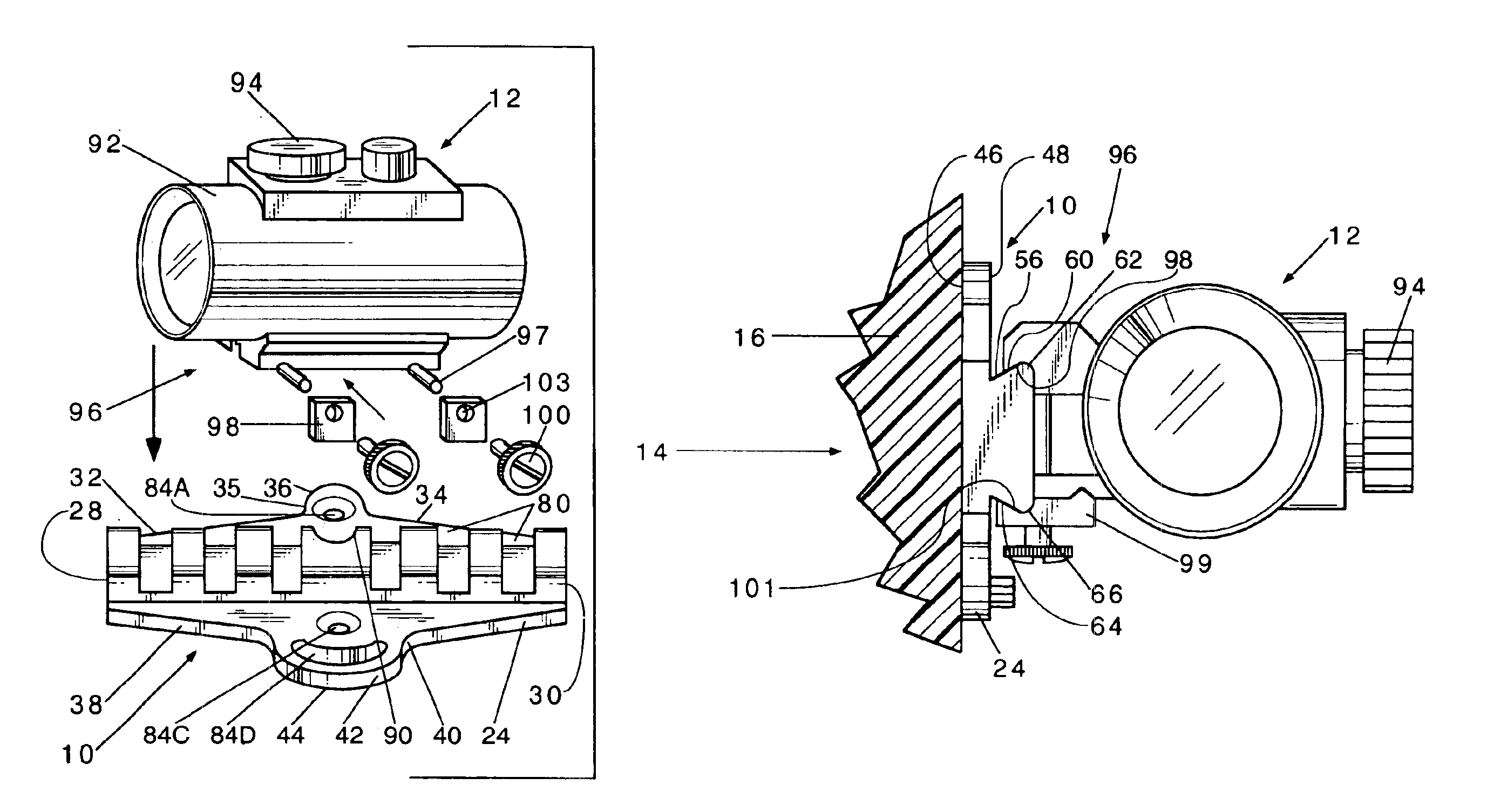
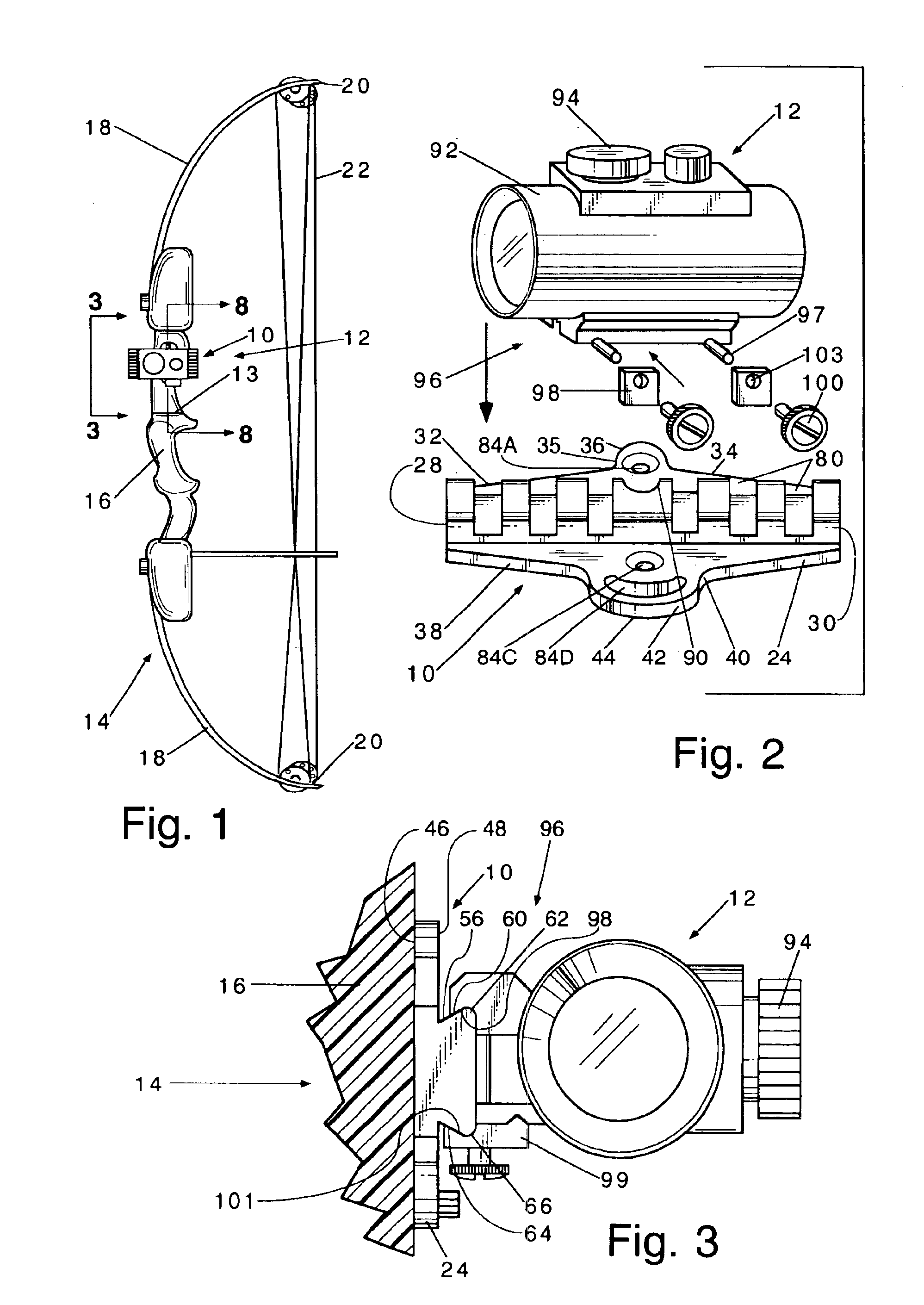
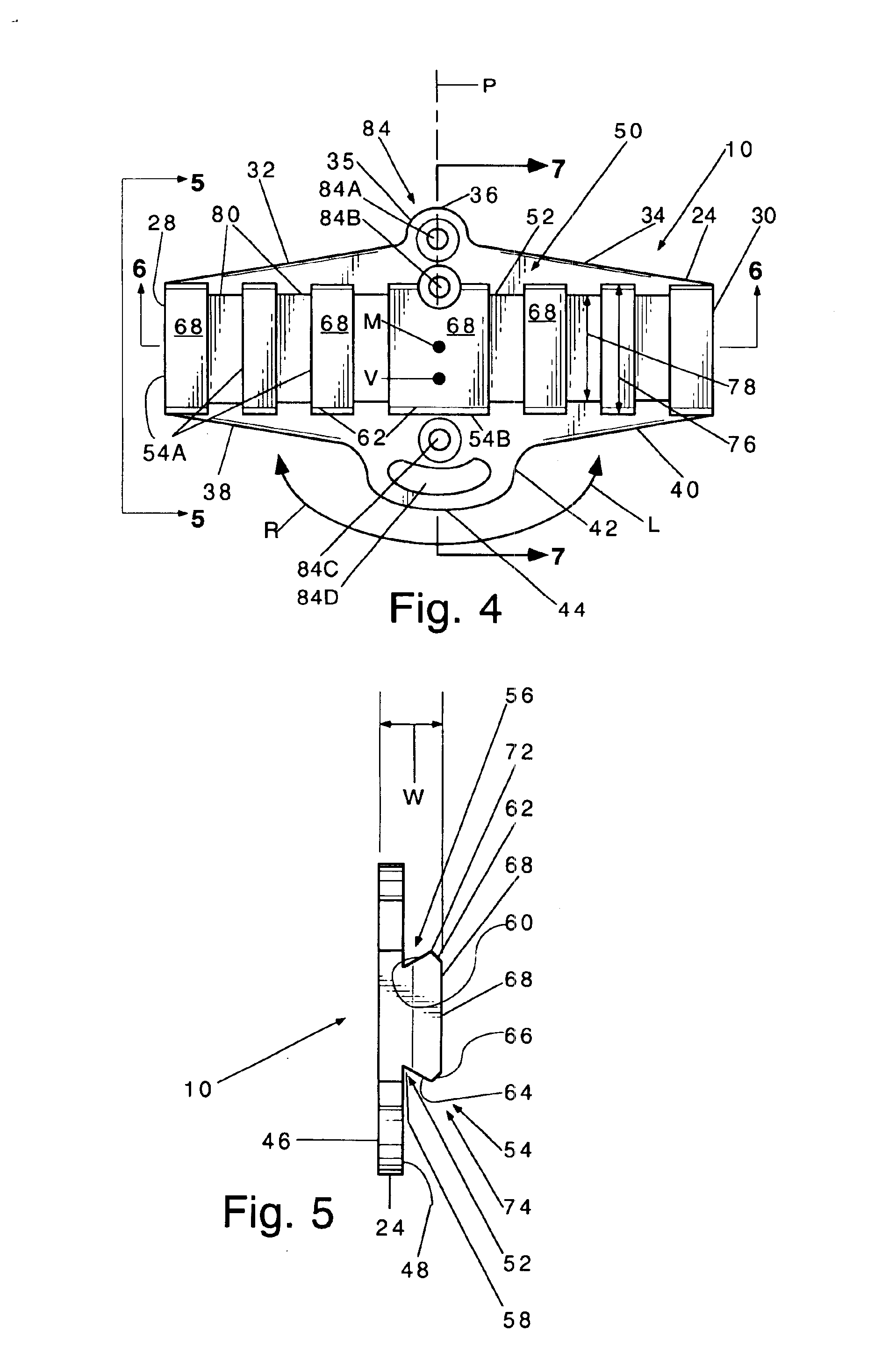
[0023]The dovetailed protrusion facilitates the slidable mounting of an archery scope which can slidably move on the dovetailed protrusion of the mount. The scope then secures to the dovetailed protrusion in a manner that allows tightening devices of the scope to set in the elongate grooves while the outer edge of the scope securely grasps the horizontal edges of the dovetailed protrusion.

Problems solved by technology

Not only are the bow sights large, protruding and easily inadvertently hit but, the quivers are particularly massive and more easily inadvertently hit jarring the bow sight out of alignment.
The use of rings provide many additional parts which can be inadvertently decoupled and / or relatively moved to disrupt the sight.

Method used


Image

  • Archery scope mount
  • Archery scope mount
  • Archery scope mount

Examples


Embodiment Construction

[0035]A scope mount, generally designated 10, constructed according to the present invention, is particularly adapted for mounting a scope 12 on a typical compound archery bow, generally designated 14, including a central riser 16 coupled to upper and lower curved bow portions 18 having terminal ends 20 spanned by a bow string 22, as usual. The riser 16 includes lateral sides 11. An arrow rest 13 is mounted on the lateral side 11 of the bow which is closest to the archer. Vertically spaced internally threaded, laterally outwardly opening, open ended threaded ferrules 17 and 19 are disposed in the riser 16 flush with the surface the lateral surface 11 adjacent the arrow rest 13. The axes of the ferrules 17 and 19 are spaced apart a distance D. The bow 14 lies in a predetermined plane 15.

[0036]The scope mount 10 includes an elongate base or plate 24 lying in a plane 26 parallel to the plane 15. The base 24 includes longitudinally spaced apart front and rear ends 28 and 30, respectivel...


PUM


Abstract

This invention relates to a one-piece lightweight, compact, low profile adjustable scope mount for mounting a sighting scope on a lateral side surface of an archery bow. The mount includes a dovetail sight mounting rail which projects perpendicular away from the bow and includes a plurality of spaced apart scope receiving channels therein. The mount is detachably swingably mounted on the bow and allows the user to adjust the adjustable mounting plate either vertically and / or horizontally. The adjustable scope mount is unitary in construction and extends a very short distance away from the inside riser of the bow whereby making it virtually impossible to inadvertently move the plate. The adjustment of fasteners is all that is required to make vertical and / or horizontal adjustments.

Description

BACKGROUND OF THE INVENTION[0001]1. Field of the Invention:[0002]This invention relates to an archery scope mount and more particularly to a new and novel light weight, one-piece low-profile mount for adjustably mounting a scope on an archery bow.[0003]2. Description of Prior Art and Objects:[0004]Many have adapted sights and telescopes, hereinafter referred to as scopes, on archery bows. The heed for a sight stems from the gravitational force placed upon the arrow as it makes its way to the chosen target. When the arrow is released from the bowstring, gravity instantly reacts, pulling the arrow toward the ground. The use of sights and scopes is an effort to compensate the gravitational effect. In order for this to happen, the sight must balance the distances over the gravitational forces to reach the goal. Many situations require the archer to determine the distance with nothing more than the archer's perception. This is the basis for the adjustability of the mounting plate of the ...

Claims


Application Information

Patent Timeline
IPC IPC(8): F41G1/467F41G1/387F41G1/00
CPCF41G1/467
Inventor MENDYK, PATRICK
Owner MENDYK PATRICK
Learn More