Electronic locking system

a technology of electronic locks and locking systems, applied in the field of electronic locks, can solve the problems of prone to corrosion of batteries, a number of drawbacks of electronic locks, and a source of power

Inactive Publication Date: 2005-05-24
VIDEX
View PDF130 Cites 90 Cited by
  • Summary
  • Abstract
  • Description
  • Claims
  • Application Information

AI Technical Summary

Benefits of technology

[0013]In a first separate aspect of the invention, an electronic lock is provided that may be used to replace conventional interchangeable core locks that employ elongate throw pins. The lock has a locking mechanism which includes a longitudinally oriented solenoid assembly which is parallel to the longitudinal rotational axis of the cylinder. The lock defines within the cylinder an elongate longitudinally aligned cavity capable of receiving the elongate throw pins.

Problems solved by technology

However, electronic locks suffer from a number of drawbacks.
First, the locks require a source of power.
Such batteries may also be prone to corrosion which can affect the internal parts of the lock.
In addition, if the battery loses power, then the lock may no longer be able to function.
Further, such wiring may not be available in some environments, such as a desk or cabinet.
Thus, the space available within such a lock is confined, limiting the size and number of components that may be used within a lock.
However, a problem arises due to the elongate throw pins used with such interchangeable core locks.
Accommodating elongate throw pins further restricts the space available within the lock.
Another difficulty with electronic locks is that they are susceptible to opening in response to sharp blows.
Another problem with electronic locks is that often a solenoid is used to move a plunger into and out of interfering relationship with the internal cylinder and the external shell.
This may result in several problems.
Another problem is that the electronic lock may be difficult to lock, since it may be difficult to align the plunger with its corresponding bore.
Another difficulty is that the lock must be protected from being opened by an externally applied magnetic field.
Yet another problem is that some electronic locks allow removal of the key during rotation of the lock.

Method used


Image

  • Electronic locking system
  • Electronic locking system
  • Electronic locking system

Examples


Embodiment Construction

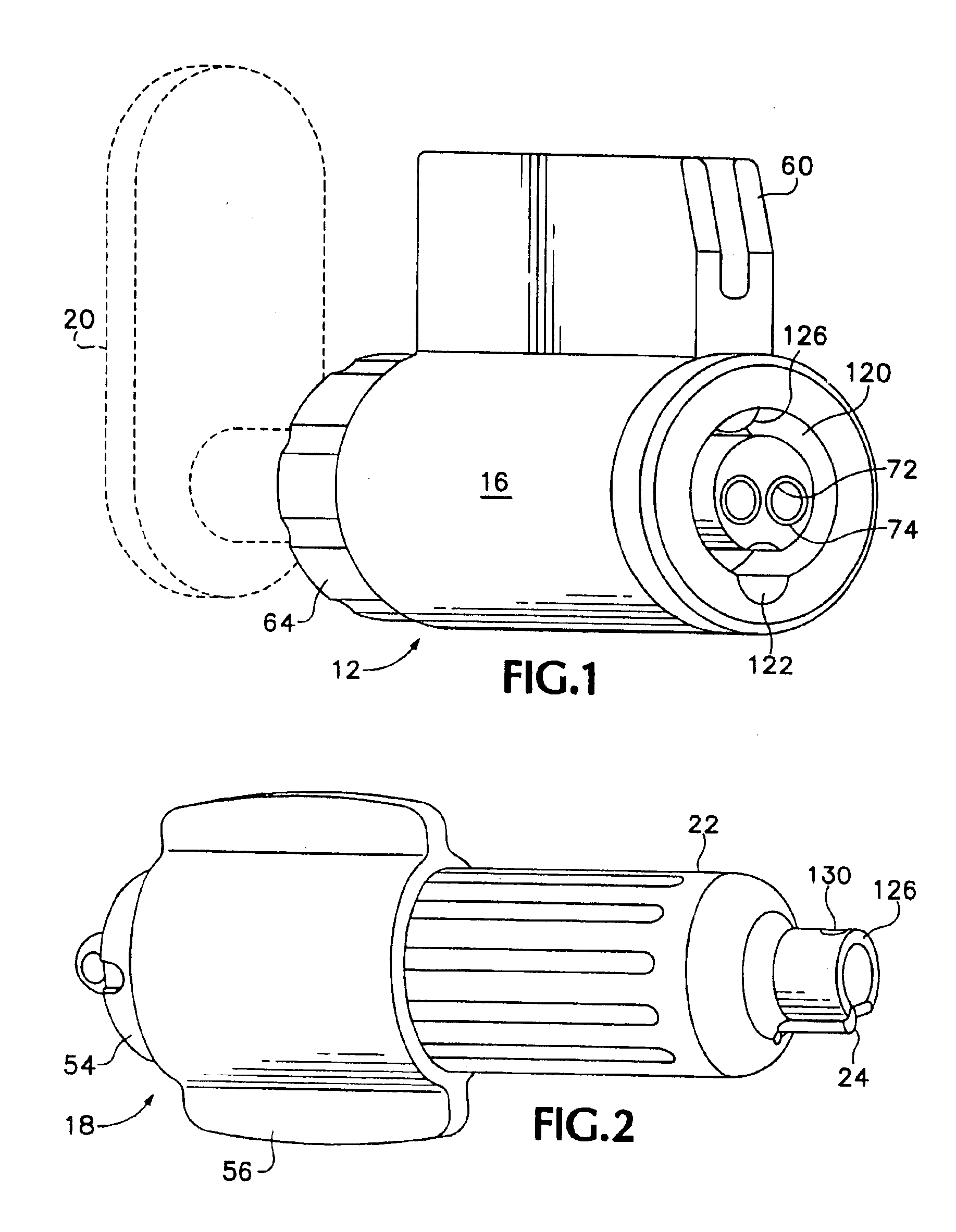
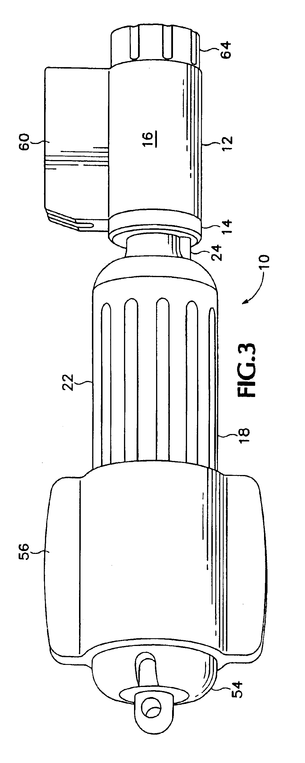
[0038]Referring now to the figures, wherein like numerals refer to like elements, FIGS. 1, 2 and 3 show an exemplary electronic locking system 10, which consists of a lock 12 and key 18. The lock 12 has a cylinder 14 that rotates within a shell 16. A bolt 20 (shown in phantom lines) is attached to the rear of the lock 12. In operation, the key 18 engages the lock 12 as shown in FIG. 3. The key 18 and lock 12 communicate electronically, so that when an authorized key 18 engages the lock 12, the cylinder 14 may be rotated within the shell 16. Rotation of the cylinder 14 causes movement of the bolt 20, enabling opening of the device that has been locked. For example, where the electronic locking system 10 is used with a desk drawer, rotation of the cylinder 14 would move the bolt 20 to a position wherein the desk drawer could be opened. The electronic locking system 10 may be used in any application where a lock would be desired, such as with doors, windows, cabinets, desks, filing cab...


PUM


Abstract

In a first aspect, an electronic lock (12) suitable for replacing interchangeable core locks has a solenoid assembly comprising a solenoid coil (280) and a plunger (290) longitudinally aligned parallel to the rotational axis (A) of the cylinder (214) of the lock (12).

Description

[0001]This application is a continuation of patent application Ser. No. 10 / 202,435, filed Jul. 22, 2002, now U.S. Pat. No. 6,604,394 B2; which is a continuation of patent application Ser. No. 09 / 784,228, filed Feb. 13, 2001, now U.S. Pat. No. 6,474,122; which is a continuation-in-part of patent application Ser. No. 09 / 491,488, filed Jan. 25, 2000, now U.S. Pat. No. 6,615,625 B2, the priority of which is hereby claimed.BACKGROUND OF THE INVENTION[0002]The present invention relates to an electronic lock.[0003]Electronic locks have many advantages over entirely mechanical locks. For example, electronic locks used in combination with a microprocessor or a computer can be programed to control the electronic lock by time of day, by authorization codes, or other factors that may be programed into the processor. When a key is lost, instead of replacing the electronic lock, the electronic lock may be reprogrammed to accept a different identification code from a different key.[0004]However, e...

Claims


Application Information

Patent Timeline
Patent Type & Authority Patents(United States)
IPC IPC(8): E05B47/06E05B17/20E05B17/00E05B11/00E05B11/02E05B47/00G07C9/00E05B15/00E05B47/04E05B49/00
CPCE05B65/0014E05B17/2092E05B47/0615E05B47/063E05B47/0649G07C9/00309E05B9/086E05B17/2084E05B47/0004E05B2047/0058E05B2047/0092G07C2009/00634G07C2009/00761G07C2209/62E05B11/02Y10T70/7079Y10T70/7102Y10T70/7136Y10T70/765Y10T70/7661Y10T70/7706Y10T70/7751Y10T70/7768Y10T70/7915
Inventor DAVIS, PAUL R.
Owner VIDEX
Why Eureka
Try Eureka