
Chain stitch multi-needle quilting machine and method to create a pattern in a quilting material

a multi-needle, quilting machine technology, applied in the field of chain stitch multi-needle quilting machine and method to create a pattern in the quilting material, to achieve the effect of relatively shor

Inactive Publication Date: 2005-05-24
NAHMASCHFAB EMIL STUTZNACKER
View PDF16 Cites 31 Cited by
  • Summary
  • Abstract
  • Description
  • Claims
  • Application Information

AI Technical Summary

Benefits of technology

[0009]Therefore the arrangement of liftable needles to chain stitch multi-needle quilting machines is intended according to the invention. It must be considered in this connection that the needles could be lifted during the quilting procedure with lock stitch machines, what is not possible with the forming of chain stitches as this would produce slip stitches facilitating the opening of the thread chain. Besides the possibility of adjusting the single needles between two positions, it is necessary with chain stitch multi-needle quilting machines in order to secure the chain stitch seam that a device to knot the needle thread with the looper thread is provided at least in the area of the adjustable needles to avoid the automatic opening of the thread chain in this area. Optionally or supplementary to this device a cutting device for the needle and / or looper thread can be provided facilitating at least the needle thread being cut with an appropriate length before or after knotting without the risk of the automatic opening of the thread chain or the chain stitch seam. Thus, the invention represents a combination of a chain stitch multi-needle quilting machine with liftable needles, a device to knot the needle thread and / or a cutting device for the needle and / or looper thread, with which the task described before can be solved in an unforeseeable and favourable way.
[0011]It makes for example an additional quilting in the peripheral area possible, especially favourable with multi-layer quilting material as an improved connection of the quilting material layers lying on top of each other is achieved.
[0015]According to another feature of the invention it is intended that the cutting device is built as cutting blade. It proved as particularly favourable arranging the cutting device at the looper or at a spreader allocated to the quilting element pair. If the cutting device is arranged at the looper, it could be brought in contact with the appropriate thread by an additional rotating movement of the looper shaft in order to cut the thread in a sufficient length from the latest connecting point between looper thread and needle thread.
[0018]Preferably the needle thread is knotted with the looper thread before or after the needle is transferred to the second lifted position. In the simplest case the knotting is effected by needle and looper thread being pulled tightly during the last stitch and thus pulled into the quilting material, for example, by the quilting material being transported while a needle thread loop is still tied around the looper. During the further transport it is favourable to release the needle and looper thread tension since otherwise the threads could break. Thereby it is prevented that the thread seam opens automatically by outer influences. Alternatively or supplementary it can be intended that the needle thread is cut after the seam and the last stitch are finished, and is located in a second position at the beginning of another pattern element. Once the needle thread being knotted with the looper thread, it can be cut relatively short. On the other hand, without knotting the needle thread with the looper thread, or if this knotting was only insufficiently executed, the needle thread is cut with a relatively long thread end.
[0019]According to another characteristic of the invention it is intended that the quilting material is moved in quilting direction, preferably before the beginning of the next pattern element, in order to pull the lengthened thread off a thread supply before the needle thread is knotted with the looper thread and / or cut. In this way, a sufficient length of the needle thread is provided that is sufficient for both the knotting with the needle thread and for the cutting procedure without the risk of an automatic opening of the thread chain and that the needle thread has a sufficient length for the next quilting of a pattern element.
[0022]Finally it is intended that the needle or needles is / are controlled by a programmable control. The programmable control preferably runs in analogy to one or more patterns. According to this, it is intended that one or more patterns, comprising preferably a multitude of pattern elements, are stored for example in a computer. The data of these patterns are transmitted to a known transport device for the quilting material and to the needles so that a fully automatic control is possible without making changings on the machine necessary during the quilting procedure.

Problems solved by technology

It must be considered in this connection that the needles could be lifted during the quilting procedure with lock stitch machines, what is not possible with the forming of chain stitches as this would produce slip stitches facilitating the opening of the thread chain.

Method used


Image

  • Chain stitch multi-needle quilting machine and method to create a pattern in a quilting material
  • Chain stitch multi-needle quilting machine and method to create a pattern in a quilting material
  • Chain stitch multi-needle quilting machine and method to create a pattern in a quilting material

Examples


Embodiment Construction

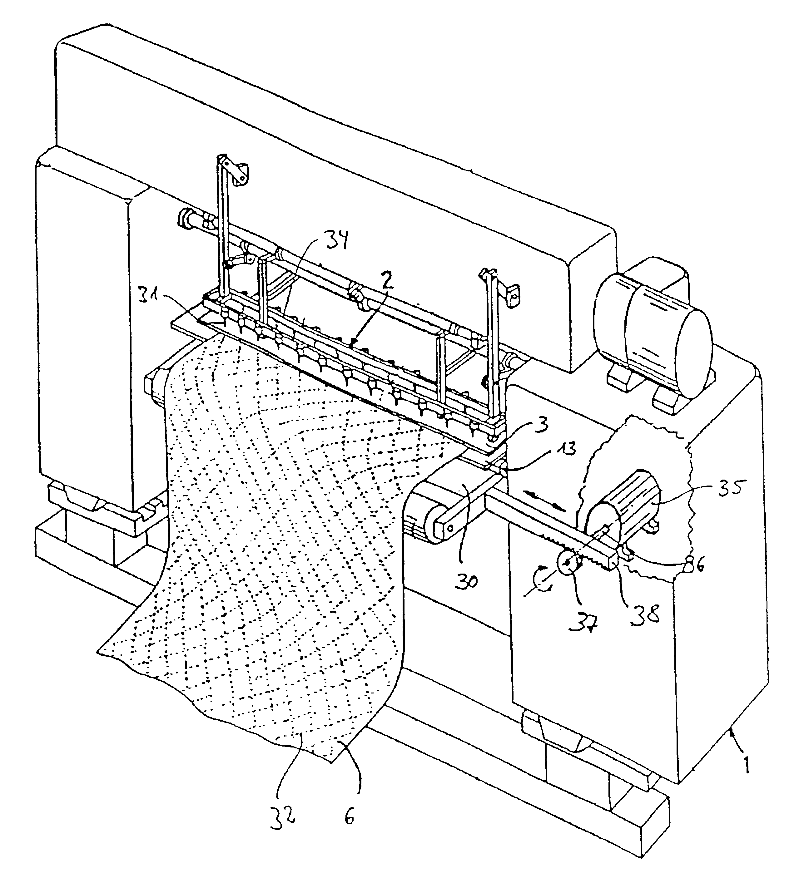
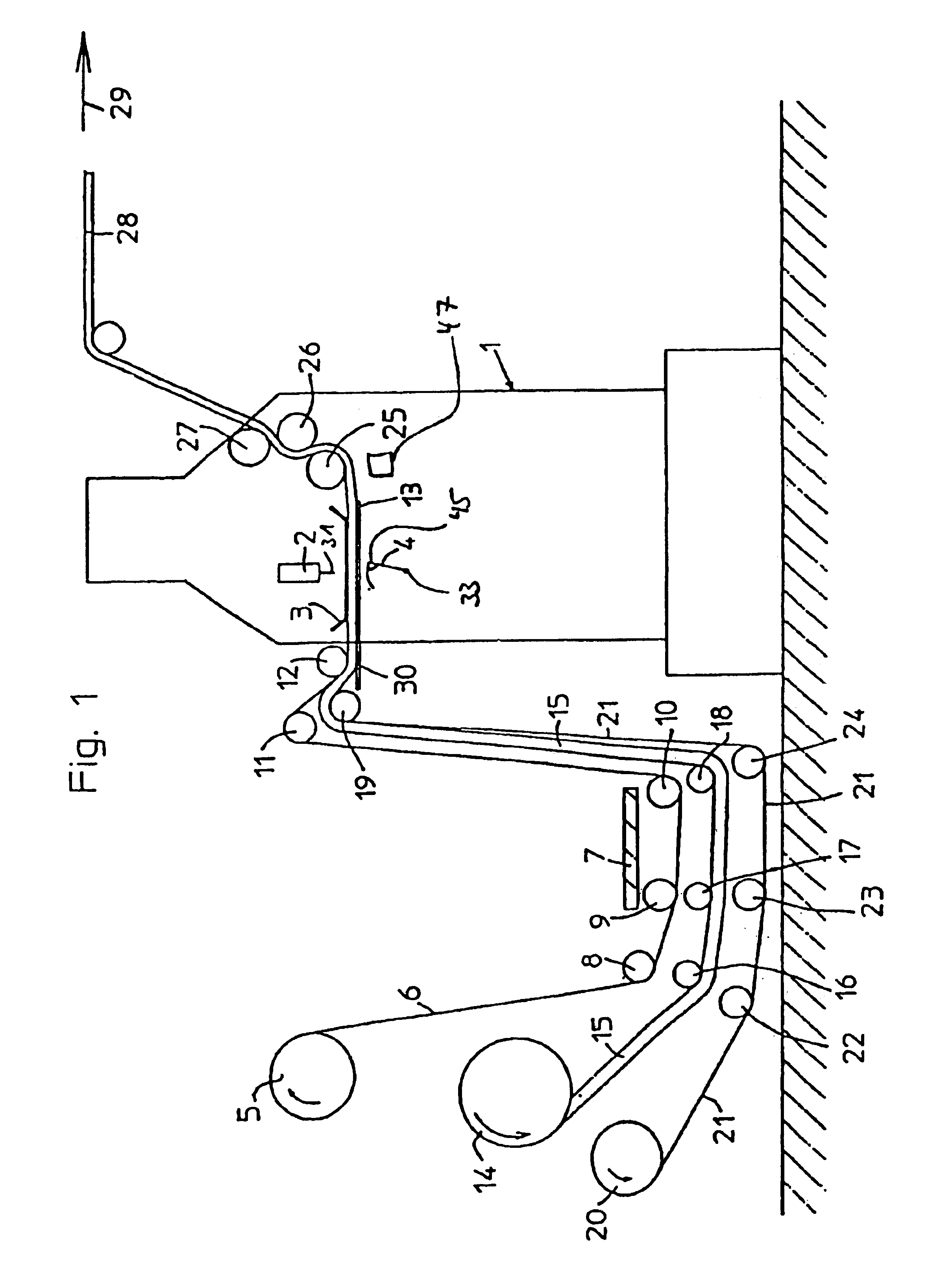
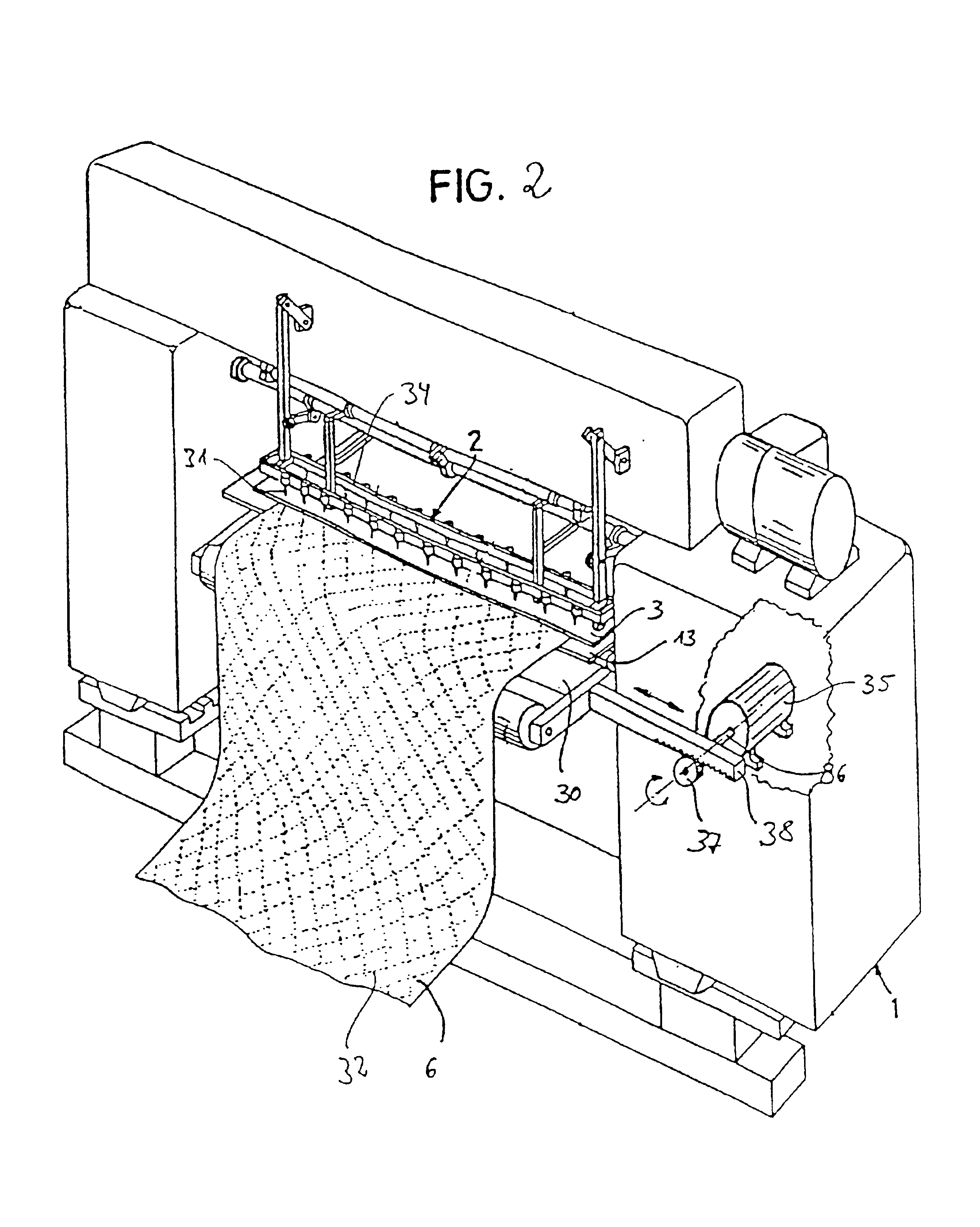
[0030]A chain stitch multi-needle machine according to FIGS. 1 and 2 comprises a machine stand 1 with a needle bar 2 in the upper section with the single driven needles 31 are essentially being arranged side by side vertically to the focal plane. Sign 3 marks a common pressure foot, 4 a looper row according to needle row 2. A needle plate 13 or a sewing table is located below the layers of the quilting material fitted together in the quilting area. This needle plate 13 serves as quilting material support.

[0031]The quilting material consists of an upper layer 6, for example fabric, ticking or something similar and is pulled off a storage roll 5 and guided below a catwalk for the operator around deflection rollers 8, 9, 10, 11 and 12 into the quilting area, that is into the area between pressure foot 3 and the needle plate 13 or the quilting material support.

[0032]This layer 6 of the quilting material consists of inelastic material. In addition, the quilting material comprises a furth...


PUM


Abstract

The invention relates to a chain stitch multi-needle guilting machine with stitch-forming quilting elements and a method for creating a pattern in a guilting material. The elements of the quilting machine are comprised of at least one needle bar with attached needles and at least one looper shaft with attached loopers. Each of the needles and the loopers have a corresponding needle thread and looper thread associated therewith, form quilting element pairs, and are driven to build chain stitches in a quilting material. At least one of the needles is adjustable between two positions and participates in the quilting procedure in a first position and does not prick into the quilting material in the second position during the quilting procedure. The quilting machine can be made to have a device to knot the needle thread with the looper thread, or a device to cut the looper thread, or both.

Description

BACKGROUND OF THE INVENTION[0001]Different multi-needle quilting machines are well-known from the state of the art technology. In this connection, so-called lock stitch multi-needle quilting machines must be distinguished from chain stitch multi-needle quilting machines. For example, U.S. Pat. No. 5,005,499 shows a lock stitch multi-needle quilting machine with one or more needle bars, each provided with a multitude of stitch forming needles. In case of this pre-known lock stitch multi-needle quilting machine, single needles can be moved, dependent on the pattern to be quilted, back and forth between two positions by means of pneumatic cylinders; whereby these needles participate in a first position in the quilting procedure, and are lifted in a second position in such a way that they do not prick into the quilting material during the quilting procedure.[0002]With the chain stitch or double chain stitch, a needle takes a thread to the deepest point of its movement and forms a thread...

Claims


Application Information

Patent Timeline
Patent Type & Authority Patents(United States)
IPC IPC(8): D05B11/00D05B65/00D05B55/10
CPCD05B11/00D05B55/10D05D2207/02D05B65/00
Inventor STUTZNACKER, KLAUS
Owner NAHMASCHFAB EMIL STUTZNACKER
Learn More